Introduction
In embedded electronics world (and indeed computing in general) interlinking circuits and processors in order to exchange information is a necessary part of creating functioning systems. In order to do this, each circuit or device must share a common communication protocol. In order to make two devices communicate, whether they are desktop computers, microcontrollers, or any other form of computer, you need a method of communication and an agreed-upon language. Serial communication is one of the most common forms of communication between computers. There are literally hundreds of communication protocols that have been defined to achieve this exchange of information. In general, they can be separated into one of two categories: parallel (meaning multiple bits are transferred at the same time on multiple “busses” or channels) and serial data (sent one single bit at a time). These notes focus on the latter, the basics of serial communication.
Note: this lesson is based in part upon Sparkfun’s serial communication tutorial. For more in-depth information on serial communication, refer to that tutorial.
Synchronous vs Asynchronous Serial
Serial communication protocols themselves can be broken into two categories: synchronous and asynchronous. The former means that there is some kind of shared clock pulse to ensure accurate transmission and receipt of information. Synchronous serial communication protocols feature a controller device which sends a clock pulse to one or more peripheral devices. The devices exchange a bit of data every time the clock changes. With asynchronous serial, you can only communicate between two devices. Each must have their own clock and keep time independently of the other. Using a mutually agreed-upon data transfer rate, devices send and listen for pulses representing the data. This works well for personal computers, mobile devices and microcontrollers because they each have their own clock crystal that keeps everything in sync.
Asynchronous Serial Communication
Usually when people talk about serial communication on the Arduino, they mean asynchronous serial (the synchronous protocols are usually referred to by their specific names, such as I2C or SPI). There are a few basic rules for asynchronous serial communication that help ensure robust and error-free data transfer. Since we are not using an external clock signal, we must specify the following:
- Baud rate
- Data bits
- Synchronization bits
- Parity bits
The protocol is highly configurable. The critical part is making sure that both devices on a serial bus are configured to use the exact same protocols.
Baud Rate
Baud rate (or data rate) is simply the speed at which the data is sent. it is usually expressed in bits-per-second (bps). Although baud rates can be just about any value within reason, the more common baud rates are 1200, 2400, 4800, 9600, 19200, 38400, 57600, and 115200. The most common of these (due to it being the most reliable) is 9600. However, any of these speeds should work with an Arduino, as long as both devices operate at the same rate.
Data Bits
The data bits, sometimes called a word, is where the real information we want to transmit is contained. The size of this word can vary from 5 to 9 bits. Often, the size is your basic 8-bit byte (this is the default on the Arduino).
Synchronization Bits
The synchronization bits are two or three special bits transferred with each chunk of data. They are the start bit and the stop bit(s). As their name implies, these bits mark the beginning and end of a packet. There’s always only one start bit, but the number of stop bits is configurable to either one or two (though it’s commonly left at one).
Parity
Parity is a simple form of low-level error checking. It comes in two flavors: odd or even. To produce the parity bit, all 5-9 bits of the data word are added up, and the evenness of the sum decides whether the bit is set or not. For example, assuming parity is set to even and was being added to a data byte like 01001111, which has an odd number of 1’s (5), the parity bit would be set to 1. Conversely, if the parity mode was set to odd, the parity bit would be 0.
Parity is optional, and not very widely used. It can be helpful for transmitting across noisy mediums, but it will also slow down your data transfer a bit and requires both sender and receiver to implement error-handling (usually, received data that fails must be re-sent).
Data Frames
Each chunk (or word) of data is actually sent in a packet or frame of bits. Frames are created by appending synchronization and parity bits to the data. Below is an example of a single serial frame.
| Start bit | Word data | Parity bit (optional) | Stop bit | |||||||
|---|---|---|---|---|---|---|---|---|---|---|
| START | BO | B1 | B2 | B3 | B4 | B5 | B6 | B7 | PB | STOP |
One of the most commonly used serial protocols is 8N1 (8 data bits, no parity, and 1 stop bit) at 9600 baud. These are the default settings for the Arduino and Processing Serial libraries (and in fact many others). Other than the baud rate, they do not need to be explicitly specified when using them.
Asynchronous Serial Hardware
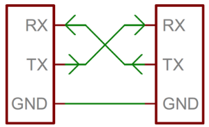
Now that we understand asynchronous serial on a conceptual level, let’s take a look at some of the physical hardware and wiring. A serial bus consists of just two wires – one for sending data and another for receiving. As such, serial devices should have two serial pins: the receiver, RX, and the transmitter, TX. Note that this is with respect to the device itself. Thus the RX from one device should connect to the TX of the other device, and vice-versa.
A serial interface where both devices may send and receive data is either full-duplex or half-duplex. Full-duplex means both devices can send and receive simultaneously. Half-duplex communication means serial devices must take turns sending and receiving. Arduinos are full-duplex devices.
Signals and Voltages
In addition to the communication rules discussed above, there are a few hardware-level rules that devices must agree to in order to communicate
- the voltage levels representing a 1 or a 0 bit
- the meaning of those voltage levels: is a high voltage 1 and a low voltage 0, or is the signal inverted?
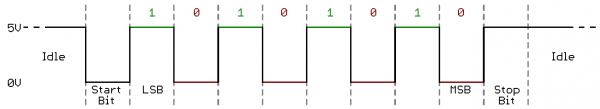
When microcontrollers and other low-level ICs communicate serially they usually do so at TTL (transistor-transistor logic) levels. TTL serial signals exist between a microcontroller’s voltage supply range – usually 0V to 3.3V or 5V. A signal at the VCC level (3.3V, 5V, etc.) indicates either an idle line, a bit of value 1, or a stop bit. A 0V (GND) signal represents either a start bit or a data bit of value 0. Arduino micrcontrollers work at TTL levels and logic.
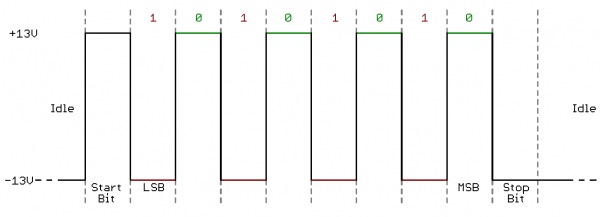
RS-232, which used to be common on desktop computers and peripherals, is kind of like inverted TTL. RS-232 signals usually range between -13V and 13V, though the spec allows for anything from +/- 3V to +/- 25V. On these signals a low voltage (-5V, -13V, etc.) indicates either the idle line, a stop bit, or a data bit of value 1. A high RS-232 signal means either a start bit, or a 0-value data bit.
Sometimes the terms TTL and RS-232 are used interchangeably. Although this is technically incorrect, you can take them both to mean asynchronous serial communication (especially between micrcontrollers and desktop/laptop computers).
UARTs
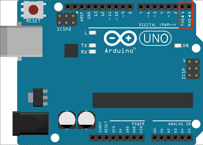
In order to manage the packaging and translation of serial data, we need an actual piece of onboard hardware. That’s where the UART (Universal Asynchronous Receiver/Transmitter) comes in. A UART is a block of circuitry responsible for implementing serial communication at the hardware level. UARTs do exist as stand-alone ICs, but they’re more commonly found inside microcontrollers. Most Arduinos have at least one UART, some (like the Mega) have more. On the Arduino Uno, the UART is accessed via the board’s USB connection and its USB to serial converter (USB or Universal Serial Bus is a synchronous serial protocol not natively supported by most Arduinos, thus requiring a converter chip.) It is also broken out through onboard hardware into two digital pins, digital 0 and digital 1.
Even though a UART is a dedicated piece of hardware, it is possible to perform serial communication tasks on (most) of the other Arduino pins. The Arduino SoftwareSerial library uses software to replicate the functionality of the UART (with some limitations).
Synchronous Serial Communication
Synchronous serial communication protocols feature a controller device which sends a continuous clock pulse to one or more peripheral devices. The devices exchange a bit of data every time the clock changes (i.e. on the rising or falling edge of the pulse). Because the clock is sent along with the data, specifying the speed isn’t important. There are two common forms of synchronous serial: Inter-Integrated Circuit, or I2C (sometimes also called Two-Wire Interface, or TWI), and Serial Peripheral Interface, or SPI. Both are supported on the Arduino platform.
I2C
The Inter-Integrated Circuit (I2C) Protocol is a protocol intended to allow multiple peripheral (or “slave”) devices to communicate with one or more controller (or “master”) devices.[1]Note: the electronics industry has used the terms “master” and “slave” to refer to controller devices and peripheral devices for decades without regard for the historical context of, and offense caused by, those terms (this is especially true of the SPI protocol). While a modern standard naming scheme has not yet emerged to replace these terms, the terms “controller” and “peripheral” will be used here and the master/slave nomenclature deprecated. It is widely used for connecting lower-speed peripheral ICs to processors and microcontrollers for short-distance communication (usually less than 1m/3.3ft).
Like UART communication, I2C only uses two wires to transmit data between devices:
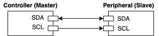
- SDA (Serial Data): The line for the master and slave to send and receive data.
- SCL (Serial Clock): The line that carries the clock signal.
Each I2C peripheral device has a unique address on the bus. When the controller wants to communicate with a particular peripheral, it sends that peripheral’s address down the SDA connection, transferring each bit on the rising edge of the clock. An extra bit indicates whether the controller wants to write or read to the peripheral that it’s addressing. The appropriate peripheral then goes into listening mode, and the controller sends a command to the peripheral. Then the controller switches its connection to the SDA line from output to input. The peripheral then replies with the appropriate data, sending each bit on the falling edge of the clock. The controller switches its connection on the SDA line back to output once it’s received all of the data. As I2C only has a single data line, it is inherently half-duplex.
Arduino micrcontrollers support I2C but only on specific pins. On the Arduino Uno, SDA is on pin A4 while SCL is on pin A5. I2C communication on the Arduino is handed via the Wire Library .
I2C Messaging
I2C data is transferred in messages, which are broken up into frames of data. There are basically two types of frames: an address frame and one or more data frames. The former is where the controller identifies the peripheral to which the message is being sent, while the latter are 8-bit data messages passed to/from controller and peripheral that contain the actual information being transmitted. A message is constructed as follows:
- Start Condition: To initiate the address frame, the controller leaves SCL high and pulls SDA low. This lets all peripheral devices know that a transmission is about to begin. Data is placed on the SDA line after SCL goes low and is sampled after the SCL line goes high.
- Address Frame: A 7 or 10 bit sequence unique to each peripheral that identifies the peripheral when the controller wants to talk to it. The address frame is always first in any new communication sequence.
- Read/Write Bit: A single bit that specifies whether the controller is sending data to the peripheral (low voltage level) or requesting data from it (high voltage level).
- ACK/NACK Bit(s): Each frame in a message is followed by an acknowledge/not-acknowledge bit. If an address frame or data frame was successfully received, an ACK bit is returned to the sender from the receiving device.
- Stop Condition: Once all the data frames have been sent, the controller will generate a 0->1 (low to high) transition on SDA after a 0->1 transition on SCL, with SCL remaining high.
Below is an example of a typical I2C message.
| Start Condition | Address frame | Data Frame 1 | Data Frame 2 | Stop Condition | ||||
|---|---|---|---|---|---|---|---|---|
| START | ADDRESS (7 or 10 bits) | READ/WRITE Bit | ACK/NACK Bit | 8 BITS | ACK/NACK Bit | 8 BITS | ACK/NACK Bit | STOP |
Signal Logic Levels
I2C allows for some flexibility in connecting devices with different I/O voltages (although this can also cause confusion). In many cases it may be possible to connect devices with different operating voltages (e.g. 3.3V & 5V) via I2C without any level shifting circuitry in between them. This usually requires the use of pull-up resistors for the lower of the two voltages. However, depending on the design of the Arduino or the I2C device, it may be prudent to use a logic level converter to ensure consistent performance and avoid damaging any device on the bus.
SPI
Serial Peripheral Interface (SPI) is an interface bus commonly used to send data between microcontrollers and small peripherals such as shift registers, sensors, and SD cards. It uses separate clock and data lines, along with a select line to choose the device you wish to talk to. SPI is good for high data rate full-duplex communication, supporting clock rates upwards of 10MHz (10 million bits/sec) compared with 1-5MHz for I2C and 2400-115200 bits/sec for UART). While SPI software implementation is usually very simple (as SPI only requires a shift register on the hardware side), its main drawback is that it requires four connections (compared to two for I2C and UART). SPI also has no error checking and only allows for a single controller (master) on the bus (I2C allows for more than one).
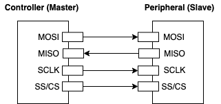
The four SPI connections are as follows:
- MOSI (Master Out Slave In): The line for the master to send data to the slave.
- MISO (Master In Slave Out): The line for the slave to send data to the master.
- SCLK (Serial Clock): The line for the clock signal.
- SS/CS (Slave Select/Chip Select): The line for the master to select which slave to talk to.
Other things to note about SPI communication:
- No start and stop bits, data can be streamed continuously without interruption
- No peripheral device addressing system (like I2C)
- Separate MISO and MOSI lines, so data can be sent and received at the same time (full-duplex)
- No acknowledgement that the data has been successfully received (i.e. no ACK/NACK bits like I2C)
- No form of error checking (like the parity bit in UART)
As with I2C, Arduino micrcontrollers have built-in hardware support for SPI communication. Although any digital pin can be used for SPI, the pins with the built-in hardware are a bit faster. On the Arduino Uno, the SPI’s SS/CS, MOSI, MISO, and SCLK connections are found on digital pins 10 to 13 respectively. SPI communication on the Arduino is handled via the SPI Library.
References
Sparkfun Serial Communication Tutorial
Arduino Serial Communications Reference
Arduino Wire Library (I2C)
Footnotes
| ↑1 | Note: the electronics industry has used the terms “master” and “slave” to refer to controller devices and peripheral devices for decades without regard for the historical context of, and offense caused by, those terms (this is especially true of the SPI protocol). While a modern standard naming scheme has not yet emerged to replace these terms, the terms “controller” and “peripheral” will be used here and the master/slave nomenclature deprecated. |
|---|