Introduction
Electricity is a natural phenomenon that occurs throughout nature and takes many different forms. For our purposes we can define electricity as the flow of electrons, or the flow of flow of electrical charge, through a conductor. We create electrical circuits using two elements: a power source and components that convert electrical energy into other forms of energy (or vice versa). We build electrical circuits to do work or to sense activity in the physical world. Electronics refers to reading or creating changes in electrical properties as way of creating and/or transmitting information. For example, a microphone changes sound pressure waves in the air to a changing electrical voltage. This process of converting one form of energy into another is called transduction. Much of the technical work of physical computing is about figuring what forms of energy are being generated and what types of transducers (e.g. sensors) you can use to read that energy.
Electricity Basics
Electricity (or more specifically electromagnetism) is a property of matter, a physical part of our universe. In order to get electricity to flow for us we need the following:
-
- we must create an electrical potential (something to move the electrical charge)
- two poles/surfaces (one with a positive charge, the other with a negative charge)
- some electrically charged medium
- a source of electrical potential (e.g. a battery)
- as soon as we have a wire (or something conductive) then we have current (i.e. flow of electrical charge)
- we must create an electrical potential (something to move the electrical charge)
To understand, manage and control electricity for practical purposes (such as electronics applications) it is vital to start by understanding the basics of voltage, current and resistance. These are the three basic building blocks you need to understand in order to work with electronics and physical computing.
When describing voltage, current, and resistance, it is common to use water and hydraulics as analogies. In this analogy, voltage represents water pressure, current is represented by the actual flow or movement of water and resistance is represented by the width/narrowness or constriction of a pipe. The water itself represents electrical charge. We will use these analogies below. (note: many of the images here are courtesy of Sparkfun. Check out their more in depth tutorial on electricity.
Voltage
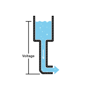
Voltage is defined as a measure of the amount of electrical potential energy between two points on a circuit. It is measured in Volts.
If we have a water tank, filled with water, at a certain height above the ground with a hose or pipe at the bottom, the pressure at the end of the pipe can represent voltage. The more water in the tank, the higher the charge and the more pressure is measured at the end of the pipe. The is in essence a battery, a place where we store a certain amount of electrical energy and then release it.
Current
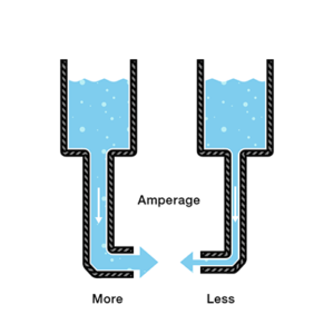
Current is a measure of the actual flow of electrons through a particular point in a circuit. It is measured in Amperes or “Amps”. We can think of current as analogous to water flowing through the pipe from the tank. The greater the pressure (voltage) the greater the flow (current) and vice-versa. If we have two tanks, each with a pipe at the bottom and each filled with the exact same amount of water (so same pressure/voltage), but with the pipe on one tank narrower than the pipe on the other, water would flow at a lower rate (i.e. lower current) from that pipe than would flow from the wider pipe. If we want the flow to be the same through both pipes, we have to increase the amount of water (charge) in the tank with the narrower hose. This would increases the pressure (voltage), thus pushing more water through. In other words, increase the voltage causes an increase in the current.
Resistance
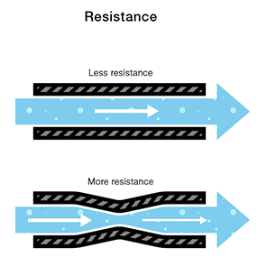
Resistance is a measure of a material’s ability to oppose the flow of electricity. It is measured in Ohms. I we consider the two pipes attached to the two tanks above, the narrower pipe is said to have a higher resistance than the wider pipe (and in fact thicker electrical wires have lower resistance — or the ability to carry more current — than thinner ones). If we were to take a section (like a portion of a circuit) of pipe and constrict it, the rate of water flow (current) would be reduced in that portion of the pipe (or circuit). This is what resistors do.
Ohms Law
As you probably realize by now, Voltage (V), Current (I) and Resistance (R) are all related, with each affecting the other. This relationship is defined by a formula, developed by physicist and mathematician Georg Ohm, called Ohm’s Law. The formula is as follows:
V = I • R
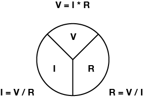
Voltage (V), Current (I) and Resistance (R) are also related to electrical power (P) (measured in watts), as follows:
P = V * I
Circuits
A circuit is a circular path of electrical flow that starts and stops at the same place and does something useful. If we connect the positive side of a voltage source, through something that does some work such as a Light Emitting Diode (LED), and back to the negative side of the voltage source, electricity (or more precisely electrical current), will flow.

But why does the electrical charge actually move? Remember that voltage is like a pump, it has a certain amount of pressure that wants to be released. Electricity wants to flow from a higher voltage/pressure to a lower voltage/pressure. If you create a conductive path between a higher voltage and a lower voltage, electricity will naturally flow along that path. And if you insert something useful into that path like an LED, the flowing electricity will do some work for you, like lighting up that LED!
Electrical Load
Every circuit has to have a source of electrical energy (e.g. a battery) and a load that uses the energy (i.e. it “loads down” the power supply because it makes it do work). All of the electrical energy in a circuit has to get used by the load. The load in the circuit above is the resistor and LED. A circuit with no load is called a short circuit. In a short circuit, the power source feeds all of its power through the wires and back to itself. The circuit burns out, which means the wires melt (if you’re lucky), or the battery and the components blow up.
Series and Parallel Circuits
Following the flow of electrical energy in a circuit can be a bit confusing. However, there are some principles that can explain this flow. Electrical components can be arranged in a circuit so that the energy flows from one component directly to the next, or they can be arranged so that the energy is split, flowing through both at the same time. When the energy flows from one to the other, the components are said to be in series. When it flows through them at the same time, they are in parallel.
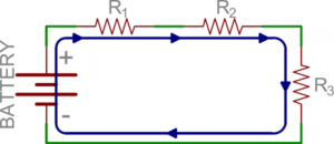
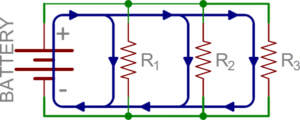
When components are added to a circuit, it changes the current and voltage relationships. When we put resistors together like as we did above, we change the way current flows through the circuit. There are a few rules to remember when trying to understand how electrical energy moves through these circuits:
Current tends to follow the path of least resistance to ground. If we think about the water analogy, water tends to flow more through a wide pipe than a narrower one. So if there are two paths in a circuit, and one has less resistance, that’s the path that the current will take.
In any given circuit, the total voltage around the path of the circuit is zero. Each component that offers resistance (resistors, LEDs, relay coils, even wires if they are long enough) lowers the voltage, and by the time you reach the end of the circuit loop, there will be no voltage left. In other words, all energy generated by the electrical power source in a circuit is converted to some other form of energy (even if it is dissipated as heat, which all electrical circuits generate to some degree).
The amount of current going into any point in a circuit is the same as the amount coming out of that point. In the series circuit above, there is a voltage drop across each resistor. The total resistance is equal to the sum of all the resistors:
Resistors in series: Rtotal = R1 + R2 + R3…
This effects the amount of current flow throughout the entire circuit (like narrowing the pipe reduces the overall water flow).
When resistors are in parallel, the voltage across them is equal but the current is divided between them. In the parallel circuit above, each resistor draws a certain amount of current (i.e. has a certain amount of water go through it). This adds up, and has the effect of reducing the total resistance. Since the divided current across the parallel resistors is equal to the total current, this means that:
Resistors in parallel: 1/Rtotal = 1/R1 + 1/R2 + 1/R3…
While it is certainly useful to think about the mathematical relationships of parallel and series circuits it can also be a bit confusing and difficult to remember. For practical purposes in this course try to remember this: resistors divide voltage when in series and divide amperage when in parallel.
Other components behave differently. For example, capacitors are the inverse of resistors: their capacitance decreases when in series and increases when in parallel. For more details refer to Sparkfun’s Serial and Parallel Circuits Tutorial.
DC and AC
There are two kinds of electrical current that are used to build circuits: Direct Current (DC) and Alternating Current (AC). In a DC circuit, current always flows one direction. In an AC circuit, the direction of current flow is reversed in a regular repeating cycle (60Hz in the U.S.). We will be working exclusively with DC circuits in this course.
References
Sparkfun: Voltage, Current, Resistance, and Ohm’s Law
Sparkfun: Series and Parallel Circuits