Introduction
This lab activity introduces various ways for making sound via CMOS logic chips and physical computing techniques. We will also look at using the Processing Sound Library to generate sound from Arduino sensor-based interfaces.
What You Will Need to Know
To get the most out of this lab, you should be familiar with the following concepts beforehand. If you’re not, review the links below:
- Arduino Analog Input
- Arduino Digital I/O
- Microcontroller Programming Basics
- CMOS Logic Chips
- Serial Communication to Processing
Items You Will Need
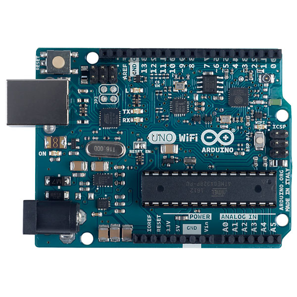
Arduino microcontroller 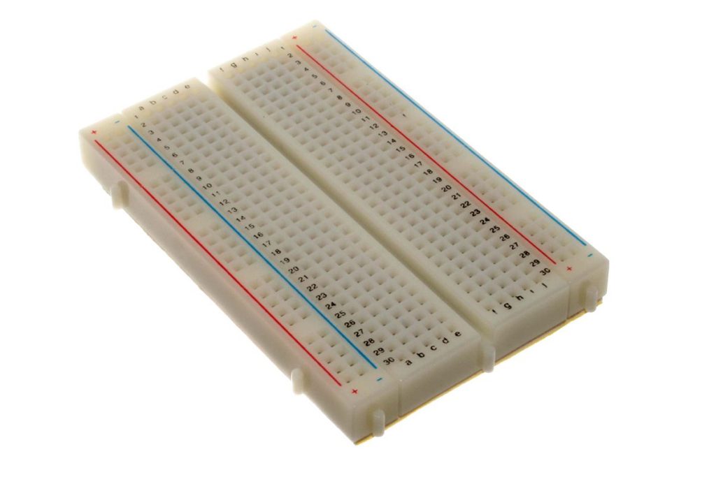
Breadboard 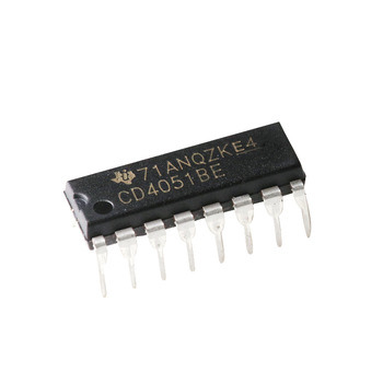
4051 multiplexer/demultiplexer 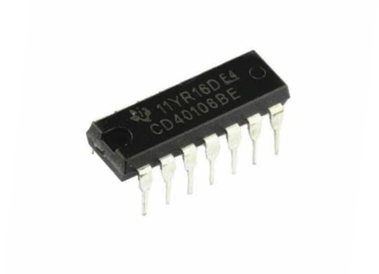
40106 Schmitt trigger hex inverter: 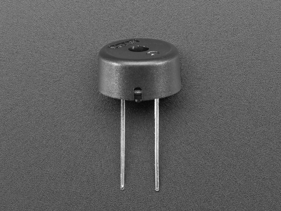
Piezo transducer 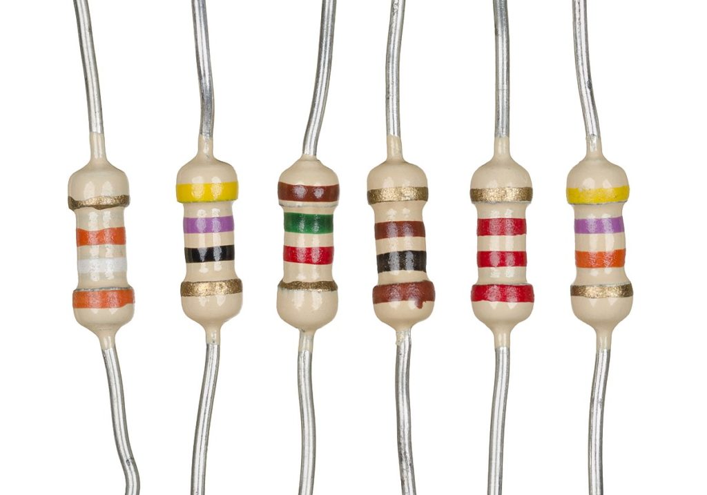
Resistors (various) 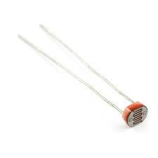
Photocell 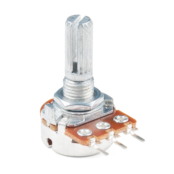
Potentiometer 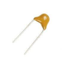
Capacitors (various) 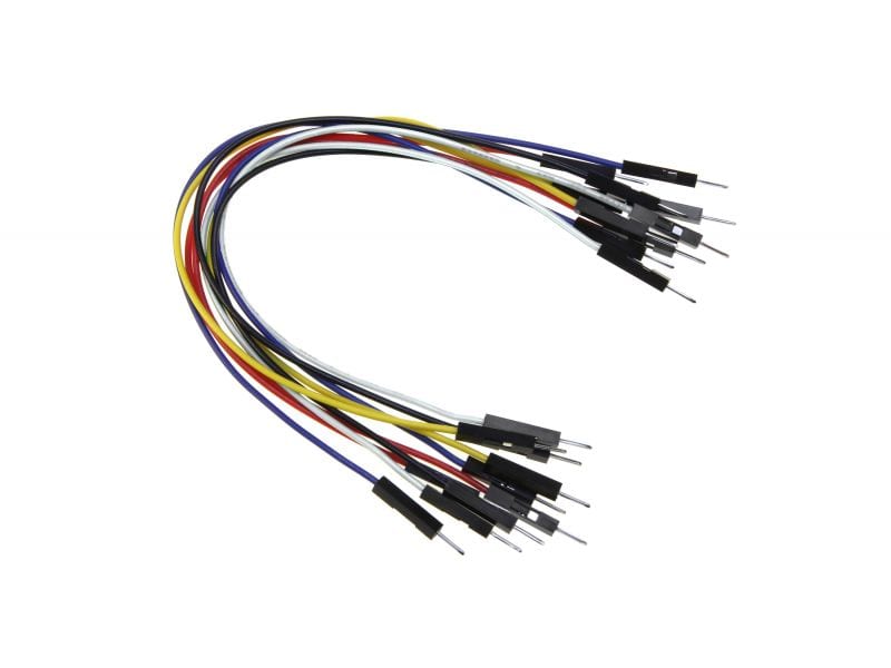
Jumper wires 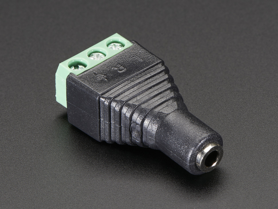
3.5mm (1/8″) Stereo Audio Jack 
Wired analog headphones (or speakers)
All of the relevant files for this lab activity can be found here
Tone Output on the Arduino
The easiest way to get sound from an electronic circuit is by using the Arduino tone() function.
Steps and observations:
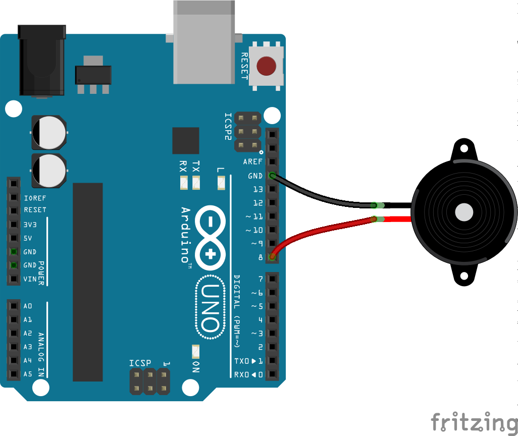
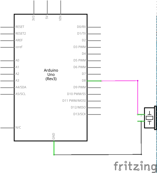
- Connect your piezo transducer to your Arduino board as shown in the images below.
- Open the toneMelody sketch under File->Examples->02.Digital->toneMelody and upload it to your board.
- Experiment with modifications to the pitches.h file (do a “Save as” first).
- Add a variable resistor or other sensor and experiment with generating and altering pitches with the sensor (can you create pitches not in the pitches.h file?).
CMOS Sound
DIY synthesizer enthusiasts have been tinkering with CMOS logic chips for decades, creating all kinds of glitchy, grungy, lo-fi synths from these chips that were intended for digital mathematical operations. We will continue this tradition of “creative misuse” here. We will use two chips: the 40106 Hex Schmitt trigger inverter (also known as the 74C14) and the 4051 analog multiplexer/demultiplexer. The 40106 is a CMOS digital logic building block consisting of six identical “inverters.” An inverter takes a logical input, 1 or 0, and puts out its opposite (so 1 becomes 0, 0 becomes 1). The 4051 (first introduced in the Logic Chips lab activity) is an analog multiplexer/demultiplexer. It can take one input and route to many outputs or take many inputs and route to one output. A note on power requirements. Many of these chips can operate under a large voltage range (e.g. 3-15V). However some chips with a different “innerfix” (e.g. 74HC14 or 74AC14 instead of 74C14), will operate under a shorter range (e.g. 3-6V). Please be aware of this before powering your chips. If in doubt use 5V (e.g. from your Arduino). As always you can review the datasheet for your specific chip to make sure.
Your First Oscillator
Steps and observations:
- Build the circuit below and connect your headphones/speakers to the audio jack.
- Turn the potentiometer to change the pitch.
- Swap out the 100nf (0.1uF) capacitor for a 1uF. Observe how it changes the frequency range of the oscillator
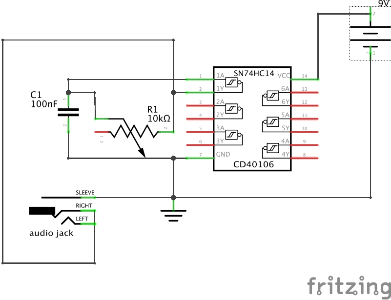
Congratulations on creating your first digital synthesizer! It’s a simple oscillator sending out square wave pulses (similar to PWM). The potentiometer allows you to sweep through a range of frequencies, while the capacitor determines what the range of those frequencies is. Too small a capacitor (less that 0.001uf) and the circuit will make sounds to high in pitch for humans to hear (and for your headphones to reproduce). Larger values (greater than 5.0uf) lower the pitch range to that of rhythm — you’ll hear the oscillation as a tick-tock instead of a buzz.
So why does this circuit oscillate? The chip outputs out the opposite of whatever signal appears at its input: if a binary “1,” represented by 9 volts (or whatever voltage you are using), is applied to the input, a “0” (0 volts) is sent to the output. That 0 flows through the resistor (a potentiometer in this case) back to the input. When the 0 appears at the input the output goes to 1, which flows back to the input and the whole process begins again. This generates a square wave. The speed of this flip-flopping (the pitch we hear) depends on the values of the resistor and capacitor.
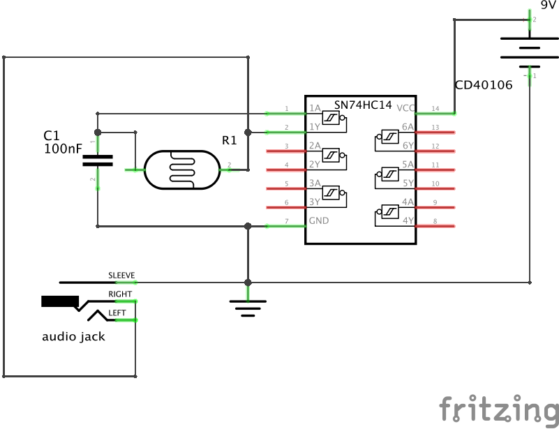
There are several ways to experiment and enhance this basic circuit. You might try swapping the potentiometer for a photoresistor, as shown in the circuit below. This will turn our simple oscillator circuit into a Theremin-style instrument controlled by light and shadow.
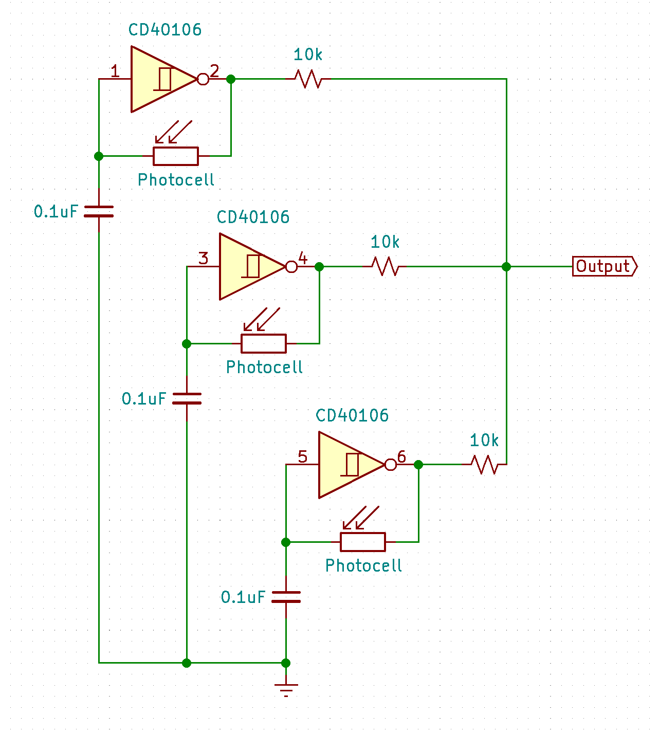
Another thing you can try is making your synthesizer polyphonic (able to produce more than one sound at a time). As the name implies, the 40106 is a Hex inverter, meaning it has six identical sections of input/outputs (and thus six oscillators). You can make an additional oscillator with any of these sections, just duplicate the connections we made for our first oscillator with another set of components, attached to another set of pins. The circuit below shows how (you can replace the photocells with other variable resistors). To mix more than one oscillator to a single audio jack, connect each output to the jack through a resistor of about 10k. Congratulations, you just created a polyphonic synthesizer and audio mixer!
Creating an Arpeggiator With the 4051
If you would like a challenge, try building the circuit below (taken from this site). This is an arpeggiator, a device that automatically steps through a sequence of notes. If you recall from the Logic Chips lab activity, the A/B/C inputs on the 4051 are control inputs. Here, pins 2, 6 and 8 from 40106 act as control oscillators, selecting which of the eight inputs of the 4051 (X0-X7) are routed to the output (X). The eight 22K resistors, wired in series, are known as a resistance ladder. They create different pitches for the fourth oscillator (pins 3 and 4 on the 40106) whose output is connected to the overall output (this is where you connect your audio jack and headphones). Depending on which of the input pins is currently active, the resistance will go up or down, which changes the pitch (remember, resistors in series have a sum resistance). By changing the frequencies of the three control oscillators (by turning the knob on their respective potentiometers), interesting control structures can appear in relation to which pitches are selected when.
If you don’t have 22k resistors you can use whatever you have, as long as they are between 10k-50k or so. Experiment with combining different resistor values. The capacitors should be around 0.1uF (but feel free to experiment with higher or lower values). 1M potentiometers are best but you can use anything between 10k-10M.
Working with Sound in Processing
If you would like to create a sound-based alternative interface, Arduino and the Processing Sound Library are a good combination. You can use Processing to create a software synth or sampler and use sensors to control their various parameters. For example, the circuit and code below uses two sensors to control parameters of simple triangle oscillator synth.
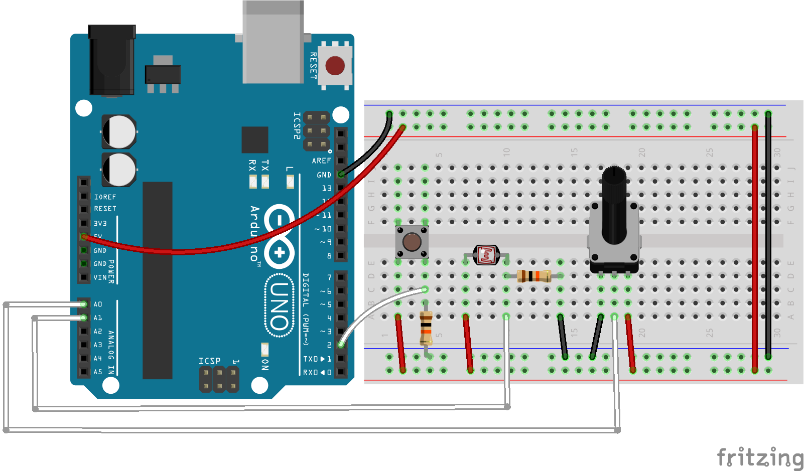
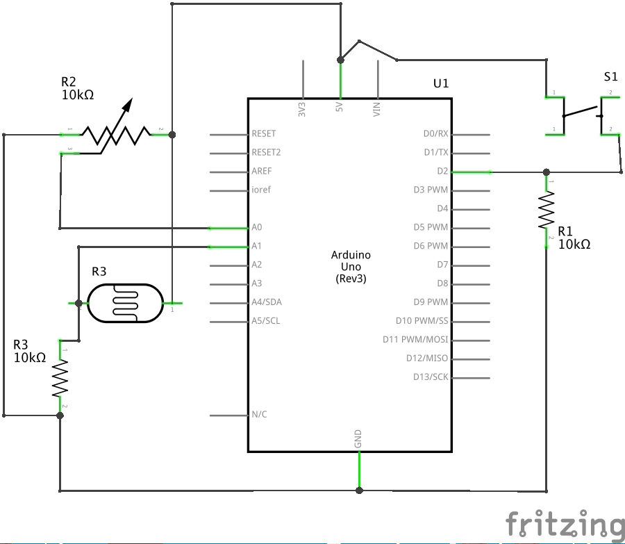
This circuit can be found here.
const int btnPin = 2; // digital input

void setup() {
   // configure the serial connection
   Serial.begin(9600);
   // configure the digital input
   pinMode(btnPin, INPUT);
}

void loop() {
   // read the sensor
   int sensorValue = analogRead(A0);
   // print the results
   Serial.print(sensorValue);
   Serial.print(",");

   // read the sensor
   sensorValue = analogRead(A1);
   // print the results
   Serial.print(sensorValue);
   Serial.print(",");

   // read the button
   sensorValue = digitalRead(btnPin);
   // print the results
   Serial.println(sensorValue);
}
This code can also be found here.
/*
 * AnalogSensorsButtonSoundOscillator
 *
 * Carlos Castellanos
 * September 30, 2020
 *
 * Example of serial communication between Processing & Arduino to control
 * the parameters of a sound oscillator.
 *
 * Arduino sends the data for three sensors as ASCII and Processing
 * uses that data to control the position of a shape on the screen
 * as well as the frequency and amplitude of a triangle oscillator.
 *
 * This sketch uses the "punctuation" method for Serial comunication.
 *
 */


import processing.serial.*; // import the Processing serial library
import processing.sound.*;  // import the Processing sound library

Serial myPort;              // The serial port

TriOsc tri;                 // Triangle wave oscillator

Reverb reverb;              // Reverb
float room=0.8;
float damp=0.3;
float wet=0.9;

float sensor0, sensor1;     // Sensors

void setup() {
  size(800, 600);

  // List all the available serial ports
  println(Serial.list());

  // Change the number in the Serial.list() array to the appropriate
  // number of the serial port that your microcontroller is attached to.
  String portName = Serial.list()[4];
  myPort = new Serial(this, portName, 9600);

  // don't generate a serialEvent() until you get an ASCII newline character
  myPort.bufferUntil('\n');

  tri = new TriOsc(this);
  tri.play();
}

void draw() {
  background(#2b9468); // green background
  fill(0);

  tri.freq(map(sensor0, 200, 800, 150, 880)); // frequency
  tri.amp(map(sensor1, 0, 1023, 0.0, 1.0));  // amplitude

  // Draw the shape
  float xloc = map(sensor1, 0, 1023, 0, width);
  float yloc = map(sensor0, 200, 800, height, 0);
  ellipse(xloc, yloc, 40, 40);
}

void serialEvent(Serial myPort) {
  // read the serial buffer:
  String myString = myPort.readStringUntil('\n');
  if (myString != null) {
    myString = trim(myString); // remove whitespace chars (e.g. '\n')
    // split the string at the commas
    // and convert the sections into integers
    int sensors[] = int(split(myString, ','));
    // now print out those three integers using a for() loop, like so
    for(int i=0; i<sensors.length; i++) {
      print("Sensor " + i + ": " + sensors[i] + "\t");
    }
    // add a linefeed at the end
    println();

    // assign the sensor values to variables
    if (sensors.length > 1) {
      sensor0 = sensors[0];
      sensor1 = sensors[1];
      // the button will send 0 or 1, which willturn the reverb on/off
      if(sensors[2] > 0) {
        wet = 0.9;
      } else {
        wet = 0.0;
      }
    }
  }
}
The code above receives data for three sensors as ASCII and uses it to control the position of a shape on the screen as well as the frequency and amplitude of a triangle oscillator. You can also get the code here.
/*
 * AnalogSensorsButtonSoundOscillator
 *
 * Carlos Castellanos
 * October 12, 2020
 *
 * Example of serial communication between Processing & Arduino to control
 * the parameters of a sound oscillator.
 *
 * Arduino sends the data for three sensors as ASCII and Processing
 * uses that data to control the frequency and attack time of a
 * triangle oscillator.
 *
 * This sketch uses the "punctuation" method for Serial comunication.
 *
 */


import processing.serial.*; // import the Processing serial library
import processing.sound.*;  // import the Processing sound library

Serial myPort;              // The serial port

TriOsc triOsc;              // Triangle wave oscillator

Env env;                    // Envelope

// Times and levels for the ASR envelope
float attackTime = 0.001;
float sustainTime = 0.01;
float sustainLevel = 0.3;
float releaseTime = 0.2;

// default frequency
float freq = 440;

// sensors
float sensor0, sensor1;

// trigger state
boolean trigger = false;

void setup() {
  size(800, 600);

  // List all the available serial ports
  println(Serial.list());

  // Change the number in the Serial.list() array to the appropriate
  // number of the serial port that your microcontroller is attached to.
  String portName = Serial.list()[4];
  myPort = new Serial(this, portName, 9600);

  // don't generate a serialEvent() until you get an ASCII newline character
  myPort.bufferUntil('\n');

  // Create the oscillator
  triOsc = new TriOsc(this);

  // Create the envelope
  env = new Env(this);
}

void draw() {
  background(0);
  fill(255);

  if(trigger) {
    // frequency
    freq = map(sensor1, 100, 800, 150, 1000);
    // play the triangle oscillator with an amplitude of 0.5
    triOsc.play(freq, 0.5);

    // The envelope gets triggered with the oscillator as input
    attackTime = map(sensor0, 0, 1023, 0.001, 0.5);
    env.play(triOsc, attackTime, sustainTime, sustainLevel, releaseTime);

    // Draw the shape
    ellipse(width/2, height/2, 80, 80);

    trigger = false;
  } else {
    // Draw the shape
    ellipse(width/2, height/2, 40, 40);
  }
}

void serialEvent(Serial myPort) {
  // read the serial buffer:
  String myString = myPort.readStringUntil('\n');
  if (myString != null) {
    myString = trim(myString); // remove whitespace chars (e.g. '\n')
    // split the string at the commas
    // and convert the sections into integers
    int sensors[] = int(split(myString, ','));
    // now print out those three integers using a for() loop, like so
    for(int i=0; i<sensors.length; i++) {
      print("Sensor " + i + ": " + sensors[i] + "\t");
    }
    // add a linefeed at the end
    println();

    // assign the sensor values to variables
    if (sensors.length > 1) {
      sensor0 = sensors[0];
      sensor1 = sensors[1];
      // the button will send 0 or 1, which willturn the oscillator on/off
      if(sensors[2] > 0) {
        trigger = true;
      }
    }
  }
}
This code takes that same Arduino sensor data and uses it to control the frequency o the oscillator and the attack time of an envelope (a pre-defined amplitude distributions over time).
Further Reading
Handmade Electronic Music: The Art of Hardware Hacking, Nicholas Collins (2009), Routledge.