Introduction
You have already been doing basic asynchronous serial communication. The Arduino Serial Monitor lets you see what is being sent and received on the serial port that the Arduino is connected to. In this lab, we will go a bit more in-depth on how to use asynchronous serial communication to send and receive data between your desktop/laptop computer and your microcontroller. After you finish this lab activity you should be ready to start writing programs in other languages/platforms on your computer to interact with your microcontroller.
What You Will Need to Know
To get the most out of this lab you should be familiar with how to program an Arduino and with the basics of serial communication. If you’re not, review the links below:
Items You Will Need
You will need the hardware listed below. For the analog sensors, you can use photocells, potentiometers or any sensor that will give you analog signals.
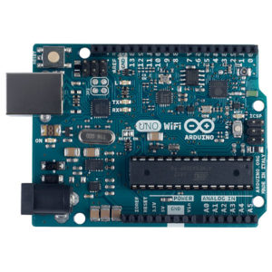
Arduino microcontroller 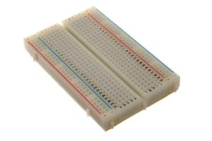
Breadboard 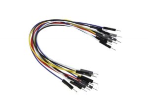
Jumper wires 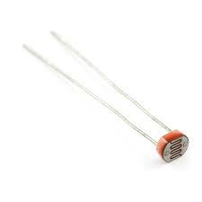
Photocell (x2) 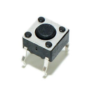
Momentary pushbutton switch 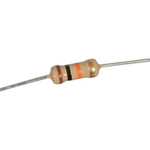
10K resistor (x3)
All the files for this lab activity are in the course code repository on Github, in this folder.
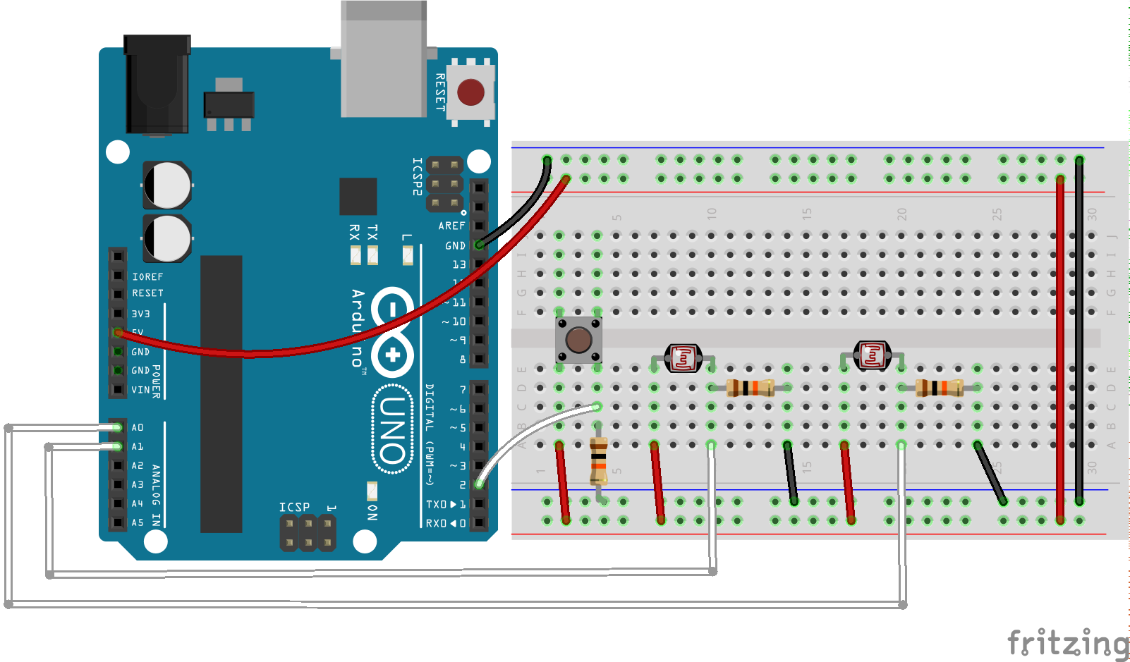
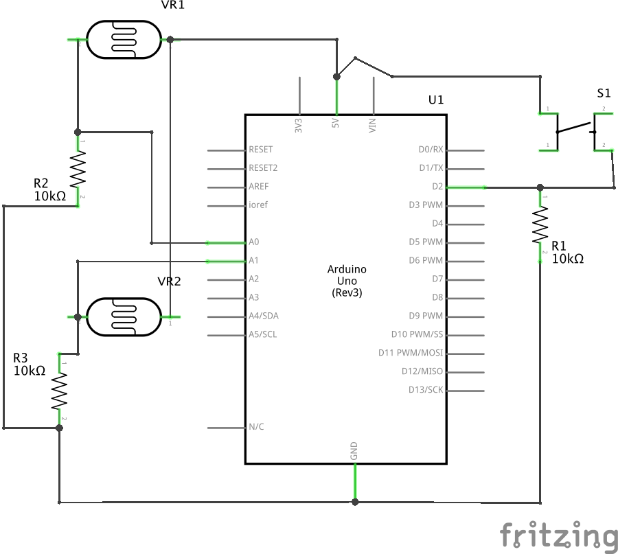
Connect the Sensors
Build the circuit below.
Initializing Communication
This lab activity focuses on asynchronous serial communication. As explained in the Serial Communication overview, communicating “serially” simply means that you are sending one single bit at a time, while the term “asynchronous” means that the two computers that are communicating are each keeping track of time independently (i.e. they each must have their own clock). Implementing serial communications involves hardware and software. The hardware UART (Universal Asynchronous Receiver/Transmitter) provides the electrical signaling between Arduino and the device it is communicating with, while software uses the hardware to send data to the connected device. There are three things the two computers need to agree upon:
- Electrical: what is the voltage of the pulses?
- Data rate: How often is a bit of data sent?
- Logic: Does low voltage mean the bit is a 0 or a 1?
Electrical and logic agreements are set for you when you use an Arduino. The data rate (or baud rate) is set in your code (you can change it, as long as it also changed on the other device). The Arduino Serial Library also insulates you from most of the hardware complexity when you write your code. There are also three connections that need to made between any two devices that want to communicate via UART:
- a transmit line from sender to receiver
- a receive line from receiver to sender
- a common ground line
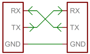
The transmit (sometimes called TX) and the receive (sometimes called RX) are relative: my transmit is connected to your receive, and vice versa (see figure below). On the Arduino Uno, digital pins 0 and 1 are used for receive and transmit. They are attached to the USB-to-serial chip on the board. When you plug the Arduino into the computer, it shows up as a USB COM device, meaning a serial communications device. When you ask for a list of serial ports, the Arduino will show up as a new port.
ASCII Text vs. Raw Binary Data
There are two main approaches that most computers use to send and receive data. They will either send the data directly, as “raw” bytes or bits or they will encode the information as a series of alphanumeric characters. Often the ASCII (American Standard Code for Information Interchange) standard is used. These days UTF (Unicode Transformation Format) is used quite a bit (especially on the web) but for Arduino communication, ASCII is still the most common way of encoding data (although UTF-8 is backward-compatible with ASCII).
So practically speaking what is the difference between ASCII and raw binary data on the Arduino? Let’s start by reading the value from one sensor (the photocell connected to A0) and sending it to the serial port:
void setup() {
   // start serial port at 9600 bps:
   Serial.begin(9600);
}

void loop() {
   int sensorVal = analogRead(A0);
   Serial.println(sensorVal);
}
If you open the serial monitor, you will see a number between 0 and 1023 scrolling down the window. That’s because Serial.println() formats the value it prints as an ASCII-encoded decimal number, with a linefeed and a carriage return at the end. A value 50, for example, uses four bytes: the characters 5, 0, and a carriage return byte and a newline byte. Meanwhile, the Serial Monitor shows you the ASCII character corresponding to each byte it receives. To change the above example to send raw binary data, we can use Serial.write().
void setup() {
   // start serial port at 9600 bps:
   Serial.begin(9600);
}

void loop() {
   int sensorVal = analogRead(A0);
   Serial.write(sensorVal);
}
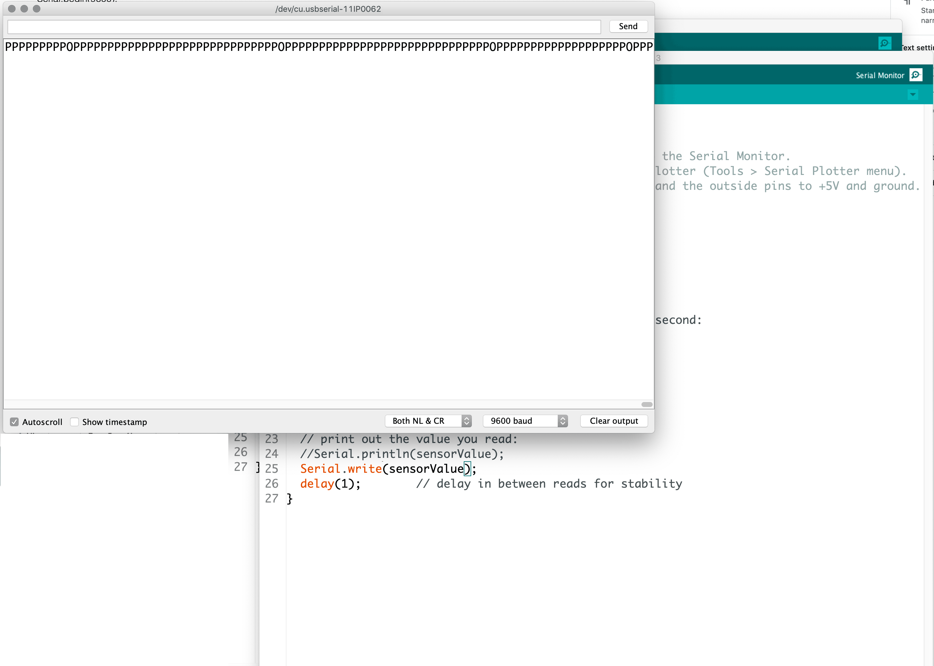
Now you get a bunch of (seemingly) garbage characters similar to the image below. Instead of encoding the bytes as ASCII characters, the Serial.write() command sends out the raw binary value of the sensor reading. The garbage characters correspond to the ASCII values the Serial Monitor is receiving. When the Serial Monitor receives a byte, it shows you the ASCII character corresponding to that byte’s value.
There is one problem however. Since the output from analogRead() ranges between 0 and 1023 (10-bit resolution), any value above 255 (8-bits/one byte) can’t fit in a single byte.[1]The ASCII table actually only includes 128 characters. Thus, Serial Monitor will likely show you characters from another character set (most likely UTF-8) for any sensor reading above 127. To get around this you can simply map the output to a range from 0-255 using the map() function or you can divide by 4. Either way this will reduce the range to 0 to 255, so it can fit in a single byte. The map() function method is shown below:
void setup() {
   // start serial port at 9600 bps:
   Serial.begin(9600);
}

void loop() {
   int sensorVal = analogRead(A0);
   int mappedValue = map(sensorVal, 0, 1023, 0, 255);
   Serial.write(mappedValue);
}
For most of the work you will be doing in this course, sending and receiving data in ASCII format is the simplest way to go. While it is a bit less efficient than sending raw binary data, it is more readable and is still plenty fast for most tasks you will need to do.
Sending Data in Many Formats
You can actually print data to the serial port in many different formats. Here is a sketch that demonstrates all the format options:
void setup() {
  // start serial port at 9600 bps:
  Serial.begin(9600);
}

void loop() {
  // read analog input, map it to make the range 0-255:
  int sensorVal = analogRead(A0);
  int mappedVal = map(sensorVal, 0, 1023, 0, 255);

  // print different formats:
  Serial.write(mappedVal); // Print the raw binary value
  Serial.print('\t'); // print a tab
  // print ASCII-encoded values:
  Serial.print(mappedVal, BIN); // print ASCII-encoded binary value
  Serial.print('\t'); // print a tab
  Serial.print(mappedVal); // print decimal value
  Serial.print('\t'); // print a tab
  Serial.print(mappedVal, HEX); // print hexadecimal value
  Serial.print('\t'); // print a tab
  Serial.print(mappedVal, OCT); // print octal value
  Serial.println(); // print linefeed and carriage return

  delay(500); // 0.5 second delay so we can see the numbers better
}
If you upload this code to your Arduino and open the Serial Monitor, you should see something like this:
K 1001011 75 4B 113
L 1001100 76 4C 114
L 1001100 76 4C 114
K 1001011 75 4B 113
K 1001011 75 4B 113
J 1001010 74 4A 112
J 1001010 74 4A 112
I 1001001 73 49 111
J 1001010 74 4A 112
K 1001011 75 4B 113
Receiving Serial Data
Up to this point we’ve been sending serial data and viewing in the Serial Monitor. In your projects you may also have to receive serial data (e.g. from Processing). Here is a simple sketch that receives a digit between 0 and 3 (corresponding to off, low medium and high speeds) and blinks the LED on pin 13 at a rate proportional to the received digit value.
/*
 * Blink the LED at a rate proportional to the received digit value
*/
const int ledPin = 13; // pin the LED is connected to
int blinkRate = 0;     // blink rate stored in this variable

void setup() {
  Serial.begin(9600); // Initialize serial port to send and receive at 9600 baud
  pinMode(ledPin, OUTPUT); // set this pin as output
}

void loop() {
  if ( Serial.available()) // Check to see if at least one character is available
  {
    char ch = Serial.read(); // read one byte from the serial buffer
    if(ch >= '0' && ch <= '3') // is this an ascii digit between 0 and 3?
    {
       blinkRate = (ch - '0');      // ASCII value converted to numeric value
       if(blinkRate <= 0) {
        blinkRate = 0; // don't want to divide by zero or the Arduino will explode (jk)
       } else {
        blinkRate = 500/blinkRate; // actual blinkrate is 500 mS dvided by non-zero received digit
       }
    }
  }
  blink();
}

// blink the LED with the on and off times determined by blinkRate
void blink() {
  if(blinkRate > 0) {
    digitalWrite(ledPin,HIGH);
    delay(blinkRate); // delay depends on blinkRate value
    digitalWrite(ledPin,LOW);
    delay(blinkRate);
  } else {
    digitalWrite(ledPin,LOW); // keep LED off if blinkRate = 0
  }
}
Upload this code to your Arduino and open the Serial Monitor. You can send messages by typing number in the output box and pressing the Send button.
Sending Values for Multiple Sensors
When sending multiple sensor values, things get a little more complicated. You must devise a way to know which value represents which sensor. For example, if you used the following loop to send your sensor values:
void loop() {
   for (int thisSensor = 0; thisSensor < 3; thisSensor++) {
      int sensorValue = analogRead(thisSensor);
      Serial.print(sensorValue);
      Serial.print(",");
   }
}
Your output would look something like this:
342,345,406,334,337,407,398
There is no way to determine which value corresponds to which sensor (the numbers just keep printing to the right without a a newline). We need to get the sensor values in order. Essentially, this entails coming up with your own protocol of sorts. Some kind of format that both the sender and receiver agree upon ahead of time.You can accomplish in two basic ways: you can use punctuation or you can use handshaking (aka “call and response”).
Punctuation
One way to send the data such that it can be interpreted clearly is to punctuate each set of data uniquely. Just as a sentence ends with a period, you can end your data with a carriage return and a newline. Using the two photocells and the button you wired up, we will send the data in sets of three — separated by a comma and ending in a new line & carriage return. Here is some code that will read the state of all three and send them out the serial port, properly formatted. Upload to your Arduino and observe.
const int btnPin = 2; // digital input

void setup() {
  // start serial port at 9600 bps
  Serial.begin(9600);
  // configure the digital input
  pinMode(btnPin, INPUT);
}

void loop() {
  // read the analog sensor
  int sensorVal = analogRead(A0);
  // print the results
  Serial.print(sensorValue);
  Serial.print(",");

  // read the analog sensor
  sensorVal = analogRead(A1);
  // print the results
  Serial.print(sensorValue);
  Serial.print(",");

  // read the button state
  sensorValue = digitalRead(btnPin);
  // print the results:
  Serial.println(sensorValue);
}
Now each grouping of three readings is separated by a newline, so whenever you get a newline, you know that the next value is the first sensor. Meanwhile each individual sensor reading is separated by a comma.
Handshaking
Punctuation helps keep your data in order, but because asynchronous serial communication is asynchronous, you can run into a problem when the sender sends faster than the receiver can read. When this happens, the receiver program slows down as the serial buffer fills up. You can manage this by implementing some form of flow control. The simplest way do to this is by using handshaking (aka call-and-response). With this method, the sending program only sends when it is told to do so, and the receiving program has to request new data every time it finishes reading what it has.
Handshaking is fairly easy to implement. Here is some code that will read the same two photocells and button as the punctuation example:
const int btnPin = 2; // digital input

void setup() {
  // start serial port at 9600 bps
  Serial.begin(9600);
  // configure the digital input
  pinMode(btnPin, INPUT);

  establishContact();  // send data establish contact until receiver responds
}

void loop() {
  // if we get a valid byte, read the sensors
  if (Serial.available() > 0) {
    // read the incoming byte
    int inByte = Serial.read();

    // read the analog sensor
    int sensorVal = analogRead(A0);
    // print the results
    Serial.print(sensorVal);
    Serial.print(",");

    // read the analog sensor
    sensorVal = analogRead(A1);
    // print the results
    Serial.print(sensorVal);
    Serial.print(",");

    // read the button state
    sensorVal = digitalRead(btnPin);
    // print the results:
    Serial.println(sensorVal);
  }
}

void establishContact() {
  while (Serial.available() <= 0) {
    Serial.println("0,0,0");   // send an initial string
    delay(300);
  }
}
When you run this and open the Serial Monitor, you will see this:
0,0,0
0,0,0
0,0,0
0,0,0
Type any character in the output box and click the Send button. You’ll get a string of sensor values at the end of your three zeros.
Type another character and click Send. It doesn’t matter what character you send, the loop will always wait for an incoming byte before sending a new set of sensor values. When you write a program to receive this format, it just has to behave the same way.
Punctuation vs Handshaking
The punctuation method for sending multiple serial values may seem simpler, but it has its limitations. You can’t easily use it to send binary values, because you need to have a byte with a unique value for the punctuation. In the example above, you’re using the value 10 (ASCII newline) as punctuation, so if you were sending your sensor values as raw bytes, you’d be in trouble when the sensor’s value is 10. The receiver would interpret the 10 as punctuation, not as a sensor value. In contrast, call-and-response can be used whether you’re sending data as raw binary values or as ASCII-encoded values.
Sometimes the receiver reads serial data slower than the sender sends it. For example, if you have a program that does a lot of graphics rendering, it may only read serial data every few milliseconds. The serial buffer will get full in that case, you’ll notice a lag in response time. This is when it’s good to switch to a handshaking method.
Regardless which approach you take, you would need to write a program that understands the protocol you create in order to do something interesting with the readings. You will see how do to that in these labs:
- Serial Output from Arduino to Processing
- Two-way Serial Communication Using an Arduino and Processing
Serial Terminal Programs
The Arduino Serial Monitor is a good basic way to see your serial communications, but it’s not the only way to view incoming serial data on your computer. There are many different serial terminal programs. Serial terminal programs allow you to send and receive messages from your computer’s serial ports. For a beginner, the Arduino Serial Monitor does the job fine, but as you get more familiar with serial communication, you may want to get to know some of these. If you want to know about a few of them, read on.
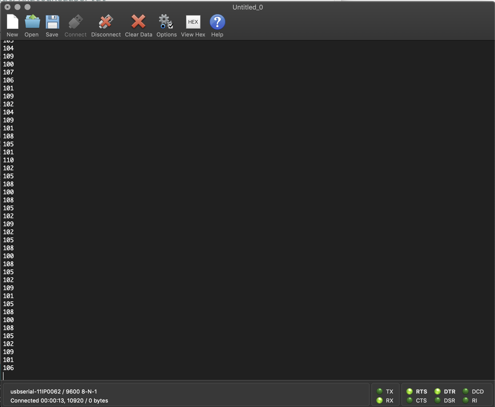
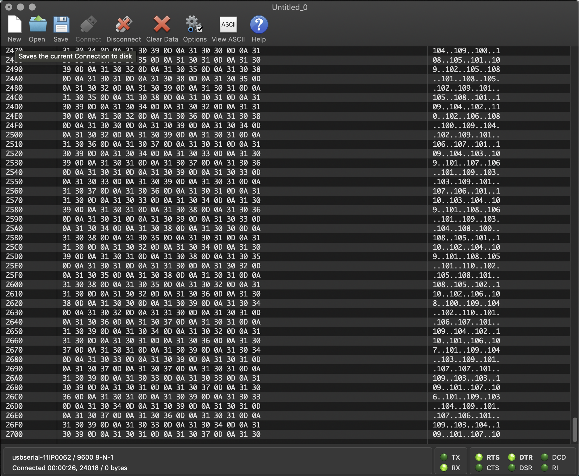
CoolTerm is a more fully-featured serial terminal program. It’s free, it’s available for OSX, Windows and Linux, and includes some features you don’t get from the Serial Monitor, like being able to open multiple ports in multiple windows, being able to view your data in ASCII or hexadecimal values, and more (see images below). PuTTY is another popular terminal application. It is Windows-only.
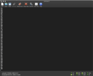
The CoolTerm serial terminal application showing the ASCII view. 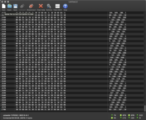
The CoolTerm serial terminal application showing the hexadecimal view.
Serial Communication on the Command Line
You can also use a command line interface as a serial terminal program on MacOS or Linux. The simplest thing you can do with serial ports on the command line is to listen for incoming serial messages. Make sure your Arduino is running a sketch with at least one Serial.print() or Serial.println() statement in your code. On MacOS, open the Terminal app, then get a list of your serial ports by typing ls -1 /dev/cu.* On Linux, you might need to type ls -1 /dev/cu* instead. You’ll get a list like this:
/dev/cu.Bluetooth-Incoming-Port
/dev/cu.lpss-serial2
/dev/cu.usbmodem14131
The Arduino is the one labeled usbmodemXXXX (or maybe usbserialXXXX), as you’ve seen before in the Arduino IDE’s Serial Monitor. To see what the Arduino is sending out, type:
cat /dev/cu.usbmodem14131
The terminal will then print out whatever the Arduino is sending. To close the port, type control-C. If you’ve got a continually repeating serial output, you may prefer to use the less command instead of the cat command. less /dev/cu.usbmodemXXXX will also print out the serial output, but it will stop after each screenful. Type the spacebar to page through multiple screens, or use the arrow keys to read up and down. Type q to exit.
Using the Command Line Program Screen
On the MacOS or Linux command line interface you can type screen followed by the name of your serial port to open the interactive serial monitor called screen. Yours might look like this:
screen /dev/cu.usbmodem-1421
The screen program will take your terminal over. You will be able to type messages to be sent out the serial port in addition to receiving them in the port. To end the screen program, type control-A control-\. Then you’ll be prompted thus: Really quit and kill all your windows [y/n]. Respond with y to quit the program.
NOTE: only one program can control a serial port at a time. When you are not using a given program, remember to close the serial port. So if you are using the Arduino Serial Monitor CoolTerm or PuTTY will give you an error and vice versa.
Footnotes
| ↑1 | The ASCII table actually only includes 128 characters. Thus, Serial Monitor will likely show you characters from another character set (most likely UTF-8) for any sensor reading above 127 |
|---|