Introduction
The constraints of conventional computer devices tend to limit the imagination when it comes to integrated computational technologies into human life. Researchers, artists and designers have experimented with ways to better interface humans and the physical world with computers. Motion, gesture, touch and all kinds of human actions — even something as simple as walking around a room — have all been beautifully integrated into interactive installations and experimental interfaces. This lab activity focuses on one particular sensory modality: distance, which can be used in all sorts of creative ways. We will look at two types of distance sensors: infrared and ultrasonic. The former measures distance by shooting a beam of infrared light at an object and calculating the time it takes to bounce back to the sensor. Ultrasonic works much the same way, except it shoots pulses of sound at very high frequencies (beyond the range of human hearing).
What You Will Need to Know
To get the most out of this lab, you should be familiar with the following concepts beforehand. If you’re not, review the links below:
Items You Will Need
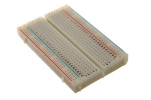
Breadboard 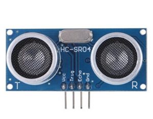
HC-SR04 Ultrasonic rangefinder 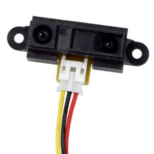
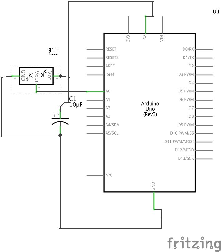
Sharp GP2Y0A21YK0F infrared distance sensor 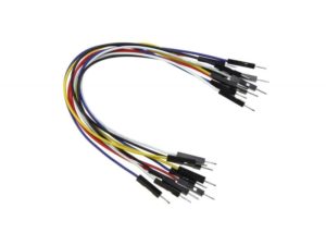
Jumper wires 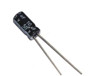
10uF electrolytic capacitor (optional)
Ultrasonic Distance Sensing
The HC-SR04 ultrasonic sensor uses sonar to determine distance to an object (kind of like bats do). The way it works is it activated by sending a HIGH pulse of 10 or more microseconds to the Trig pin. The sensor will then sends a signal (an 8 cycle burst of ultrasound at 40 kHz). When signal hits an object, it is reflected back and HIGH pulse is generated from the Echo pin. We can read this pulse on the Arduino via the pulseIn() function. You can calculate the distance through the time interval between sending the trigger signal and receiving the echo signal. This is possible because we know the speed of sound velocity through air. Here are some of the specifications of this sensor. You can also read the datasheet.
- Power Supply: +5V DC
- Current during measurement: 15mA
- Measuring Angle: 15°
- Ranging Distance: 2cm – 400cm (although 10cm – 300cm is more realistic)
- Ultrasonic Frequency: 40 KHz
- Resolution: 0.3cm
- Trigger Input Pulse width: 10uS
- Dimension: 45mm x 20mm x 15mm
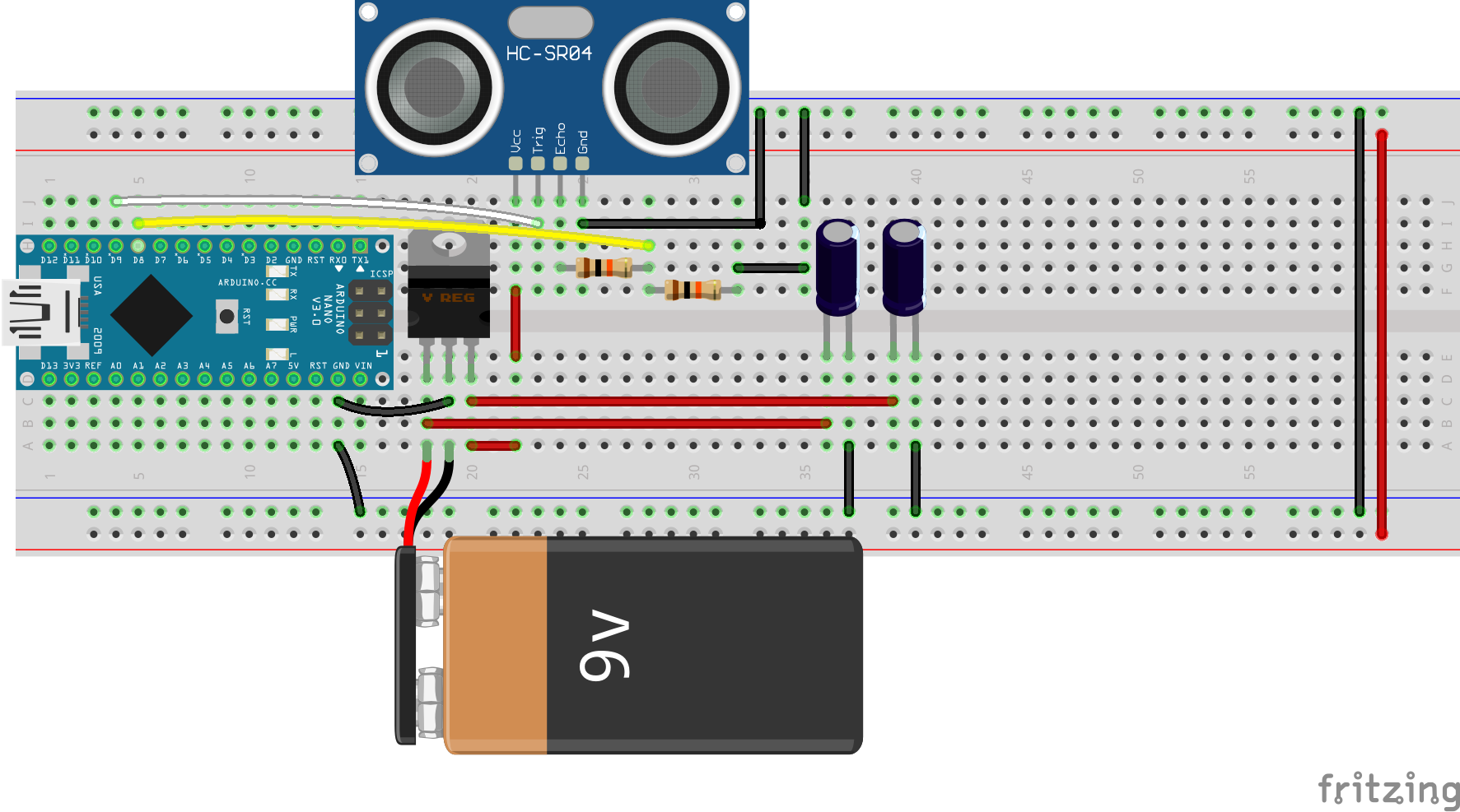
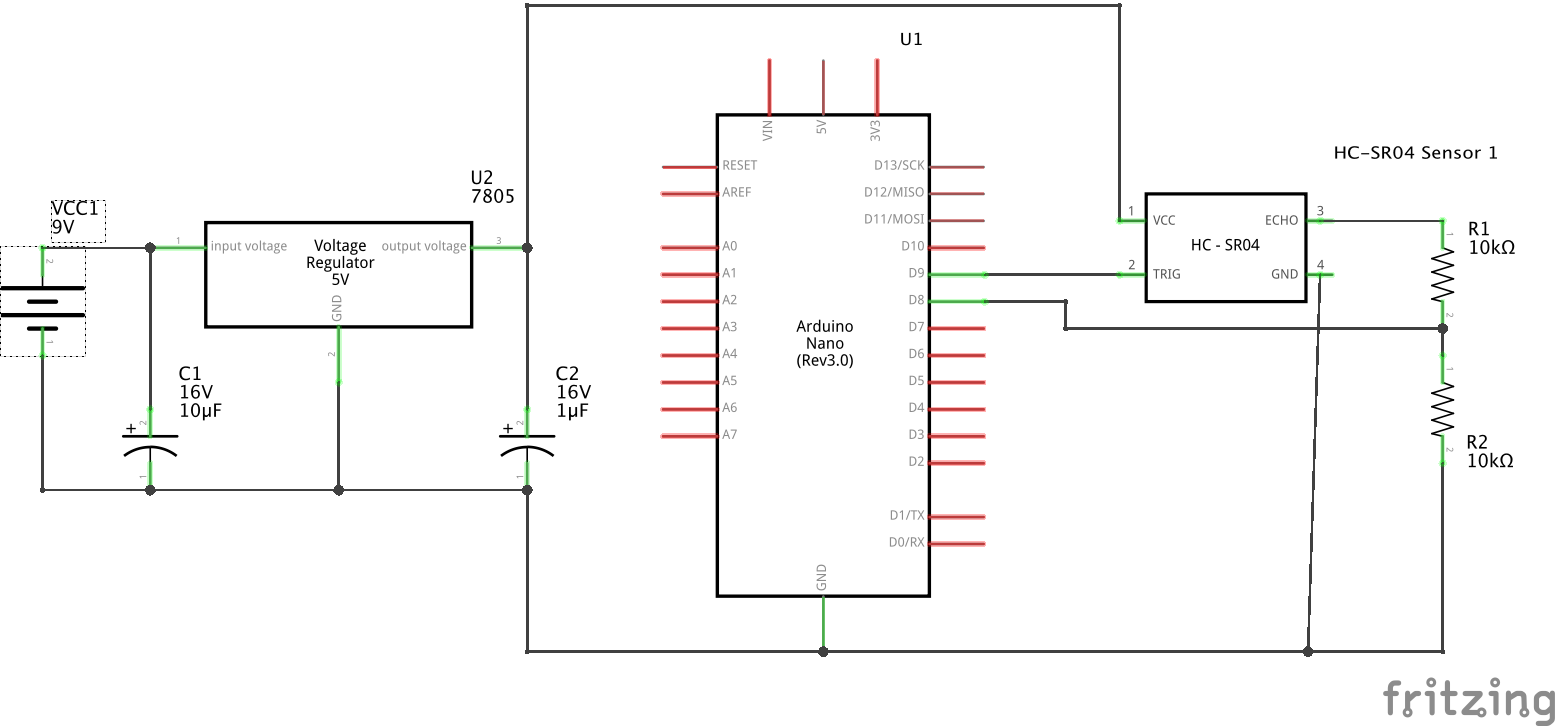
Note that the HC-SR04 requires powering from 5V for best results. While the Trig signal can be 3V or 5V, the ‘return’ Echo signal requires 5V logic. Thus if you are using a 3.3.V Arduino (like the Nano 33 IoT) you should use two 10K resistors to create as a voltage divider to convert the 5V logic level to a safe 2.5V that you can read with your 3.3V Arduino. The two bottom images show you how.
Steps and observations:
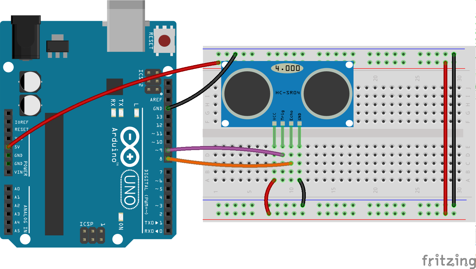
- Build the circuit below.
- Upload the code below to your Arduino.
- Select the Serial Monitor and observe the changes in distance as you move an object closer and further away from the sensor.
- Determine the highest and lowest values observed.
- Experiment by changing the angle of the object with respect to the sensor.
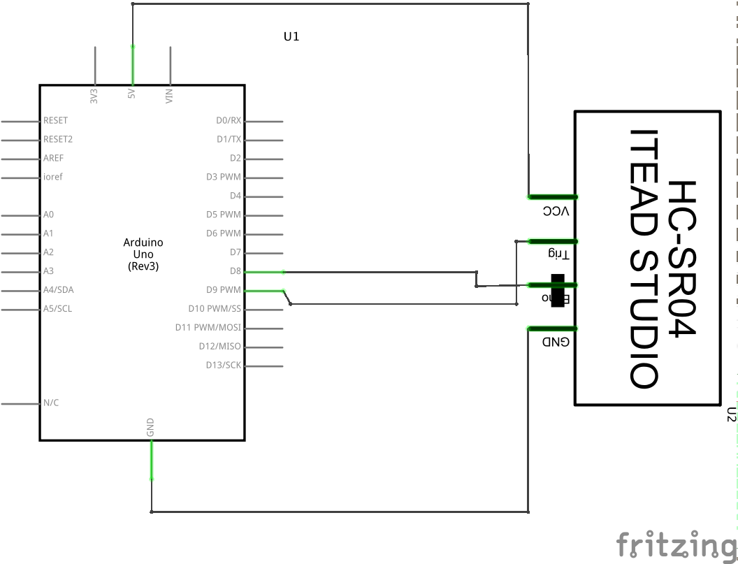
If you have a 3.3V Arduino, you must use this circuit:
/*
 *
 * Testing the HC-SR04 ultrasonic sensor
 *
    Ultrasonic sensor Pins:
        VCC: +5VDC
        Trig : Trigger (INPUT) - Pin 9
        Echo: Echo (OUTPUT) - Pin 8
        GND: GND
 */

int trigPin = 9;    //Trig
int echoPin = 8;    //Echo
long duration, cm, inches;

void setup() {
  //Serial Port begin
  Serial.begin (9600);
  //Define inputs and outputs
  pinMode(trigPin, OUTPUT);
  pinMode(echoPin, INPUT);
}

void loop() {

  // The sensor is triggered by a HIGH pulse of 10 or more microseconds.
  // Give a short LOW pulse beforehand to ensure a clean HIGH pulse:
  digitalWrite(trigPin, LOW);
  delayMicroseconds(5);
  digitalWrite(trigPin, HIGH);
  delayMicroseconds(10);
  digitalWrite(trigPin, LOW);

  // Read the signal from the sensor: a HIGH pulse whose
  // duration is the time (in microseconds) from the sending
  // of the ping to the reception of its echo off of an object.
  duration = pulseIn(echoPin, HIGH);

  // convert the time into a distance
  // we need distance traveled (cm & in) per microsecond
  // distance traveled by sensor is calculated via the following formula:
  // distance = duration * speedofSound...
  // however, time taken is actually to and from the ultrasonic sensor
  // (First the sound travels away from the sensor
  // and then it bounces off of a surface and returns back)
  // we only need half of that distance.
  // Therefore travel time is taken as duration/2:
  // distance = (duration/2) * speedofSound
  //
  // The speed of sound at sea level in dry air at 20°C (68°F)
  // is 343.51 meters/second or 1,127 ft/second (that's close enough)
  // this is equivalent too:
  // 34351 cm/sec
  // 34.351 cm/msec
  // 0.034351 cm/microsec OR 1/0.034351 = 29.11 microsecs/cm
  // 13524 in/sec
  // 13.524 in/msec
  // 0.013524 in/microsec OR 1/0.013524 = 73.94 microsecs/in
  // for more visit: https://en.wikipedia.org/wiki/Speed_of_sound

  // The pulseIn() function returns the length of a pulse in microseconds
  // so we use 29.11 microsecs/cm and 73.94 microsecs/in to calculate the
  // distance in centimeters and inches respectively.
  cm = (duration/2) / 29.11; // (duration/2) * 0.034351 will also work
  inches = (duration/2) / 73.94; // (duration/2) * 0.013524 will also work

  Serial.print(inches);
  Serial.print("in, ");
  Serial.print(cm);
  Serial.print("cm");
  Serial.println();

  delay(250);
}
Breadboard diagrams, schematics and Arduino code are available at: https://github.com/carloscastellanos/teaching/tree/master/Arduino/Sensors/Ultrasonic
Infrared Distance Sensing
The Sharp GP2Y0A21YK0F infrared distance sensor uses a beam of infrared light, reflected off of an object to measure its distance.[1]This type of IR sensing is known as “active” IR. Passive Infrared (PIR) sensors work under different principals and are typically used to measure movement, not distance. These sensors are not covered in this lab activity. For more see this link. The distance is calculated using triangulation of the beam of light. First, the device emits a narrow beam of infrared light. After reflecting off of an object, the beam is directed through a second lens on a position-sensible photo detector (PSD). The conductivity of this PSD depends on the position where the beam falls. This conductivity is then converted to a voltage, which we can read via the Arduino analogRead()function. Below are some of the specifications of this sensor. You can also read the datasheet.
- Power Supply :+4.5 – 5.5V DC
- Average current consumption: 30mA
- Distance measuring range: 10 cm to 80 cm
- Dimension: 29.5mm x 13mm x 13.5mm
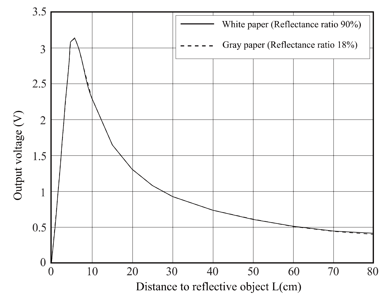
One important thing to note about this sensor is that its output is non-linear. The graph below (taken from the datasheet) shows why the usable detection range starts at ~10cm (4in). Notice that the output voltage from a distance of 2cm (.78in) away is the same as the output voltage for a distance of 28cm (11in). The usable detection range, therefore, starts after the peak at ~10cm or 2.3V. The total voltage range of the sensor is about 0-3V.
For this lab activity we will use a third-party library to calculate the distance. However if you want to challenge yourself, try calculating the distance without using a third-party library. Look at the comments in the code below for guidance.
Steps and observations:
- Install the SharpIR library form the Arduino Library manager (Sketch>Include Library>Manage Libraries…, search for “SharpIR”)
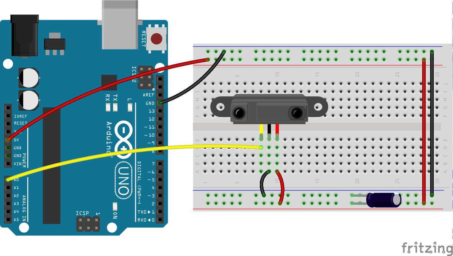
- Build the circuit below.
- Upload the code below to your Arduino.
- Select the Serial Monitor and observe the changes in distance as you move an object closer and further away from the sensor.
- Determine the highest and lowest values observed.
/*
 * GP2Y0A21YK0F_test
 *
 * Example of using SharpIR library to calculate the distance beetween the sensor and an obstacle
 *
 * Carlos Castellanos
 * June 22, 2020
 *
 * based on code by Giuseppe Masino: https://github.com/qub1750ul/Arduino_SharpIR
 *
 * -----------------------------------------------------------------------------------
 *
 * Things that you need:
 * - Arduino
 * - A Sharp IR Sensor
 *
 *
 * The circuit:
 * - Arduino 5V -> Sensor's pin 1 (Vcc)
 * - Arduino GND -> Sensor's pin 2 (GND)
 * - Arduino pin A0 -> Sensor's pin 3 (Output)
 *
 *
 * See the Sharp sensor datasheet for the pin reference, the pin configuration is the same for all models.
 * Here is the datasheet for the model GP2Y0A21YK0F:
 * http://sharp-world.com/products/device/lineup/data/pdf/datasheet/gp2y0a21yk_e.pdf
 *
 *
 *
 * BONUS:
 * Try calculcating the distance without using a third-party library
 * First convert the analog reading (which goes from 0 - 1023) to a voltage (0 - 5V):
 * float voltage = sensorValue * (5.0 / 1023.0);
 *
 * To get the distance (in cm), look at Fig. 2 in the datasheet which shows the distance to
 * voltage characteristics of the sensor. You can see that between 10 & 80cm it follows an
 * exponential curve. If you can figure out a function for that curve you will have your
 * distance formula. This is the formula I came up with: 27.3 * (voltage^-1.2)
 * float distance = 27.3 * pow(voltage, -1.199)
 *
 * You can also try the formula used in the library (which doesn't convert the analog readings to a voltage)
 * distance = 4800 / (sensorValue - 20)
 *
 * You can use the graphing program (like Grapher that comes with MacOS), MS Excel or try a web-based tool:
 * https://www.desmos.com/calculator
 *
 * Remember this only works for values between 10 & 80cm, so you must account for this in your code
 *
 */

//import the library in the sketch
#include <SharpIR.h>

//Create a new instance of the library
//Call the sensor "sensor"
//The model of the sensor is "GP2Y0A21YK0F"
//The sensor output pin is attached to the pin A0
SharpIR sensor(SharpIR::GP2Y0A21YK0F, A0);

void setup() {
  Serial.begin(9600); //Enable the serial comunication
}

void loop() {
  int distance = sensor.getDistance(); //Calculate the distance in centimeters and store the value in a variable

  // Print the measured distance to the serial monitor:
  Serial.print("Distance: ");
  Serial.print(distance);
  Serial.println("cm");
  delay(500);
}
Notes:
The capacitor in this circuit is known as a decoupling capacitor. It is connected between power & ground and helps smooth out voltage spikes and noise from the power supply. The datasheet for the GP2Y0A21YK0F recommends a 10uF or higher capacitor for use with its device but it is a good idea to use one on every circuit you build.
Breadboard diagrams, schematics and Arduino code are available at: https://github.com/carloscastellanos/teaching/tree/master/Arduino/Sensors/IR
Discussion
The ability to simply move about in space freely — and do the kinds of things humans do in normal physical and social spaces — as a means of accessing and interacting with digital information systems still seems like difficult challenge. To accomplish this goal researchers are working to develop systems that can track and interpret the motions of humans and facial and body gestures via video analysis, infrared, ultrasonic, and other kinds of sensor technologies. Our physical actions, movements gestures, postures and so on, convey extraordinary amounts of meaning that computers still do not understand very well.
Consider this when you design your interfaces. How can proximity to an object or to one or more locations in a space for example — and how that proximity changes over time (e.g. quickly, slowly, in an particular pattern, etc) — be used to convey meaning or design the parameters of an experience, especially when the responsiveness of the system is considered.
Further Reading
How to use an HC-SR04 Ultrasonic Distance Sensor with Arduino
The Right Tool for the Job: Active and Passive Infrared Sensors
Constructing Experience: Interface as Content, David Rokeby