Introduction
Accelerometers measure changes in acceleration, which is the rate by which the velocity of an object changes over time. Accelerometers can be used to measure the tilt/orientation of an object with respect of the Earth, the force of a hit or the rate at which an object is rising or falling. Often accelerometers are part of Inertial Measurement Unit (IMUs), electronic devices that measure force, angular position and orientation of an object using a combination of accelerometers, gyroscopes, and sometimes magnetometers. They are common in mobile devices, automobiles, spacecraft, unmanned aerial vehicles and more. IMUs have become increasingly common in microcontroller projects as well. In fact some Arduino boards, such as the Arduino Nano 33 IoT and the Arduino Uno Wifi Rev 2, have built-in IMUs. In this lab activity, you will learn a few principles of working with these sensors, such as how to retrieve and display readings from the accelerometer. We will demonstrate the internal IMU on the Arduino Nano 33 IoT and the Adafruit Flora LSM303 accelerometer + compass (magnetometer) board.
What You Will Need to Know
To get the most out of this lab, you should be familiar with the following concepts beforehand. If you’re not, review the links below:
Items You Will Need
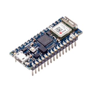
Arduino Nano 33 IOT 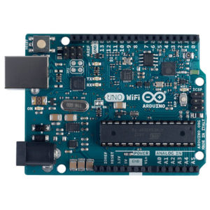
Arduino microcontroller 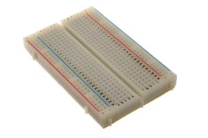
Breadboard 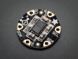
Adafruit FLORA LSM303 Accelerometer+Compass 
Jumper wires
Background Information
Determining Orientation With an Accelerometer
Orientation refers to the relative position and heading of an abject. If you are level with the Earth, a compass/magnetometer is great for this. If you are not level, you need to know your tilt relative to the Earth as well. In navigational terms, tilt is referred to as attitude, and there are two major aspects to it: roll and pitch. Roll refers to how you’re tilted side-to-side. Pitch refers to how you’re tilted front-to-back. Roll, Pitch, and Yaw refer to angular motion (rotation) around the X, Y, and Z axes respectively.
Three-axis accelerometers measure the linear acceleration of a body on each axis. They don’t give you the roll, pitch, or yaw directly. However, you can calculate the roll and pitch when you know the acceleration along each axis. That calculation takes some tricky trigonometric calculations that rely on the fact that the force of gravity always acts perpendicular to the surface of the Earth, which you can use to calculate the roll and pitch (the magnetometer can give you the yaw). Regardless of the accelerometer used however, angle readings aren’t always accurate, and can be quite noisy. There are many reasons for this but basically there are forces acting on the accelerometer besides gravity. As you move the accelerometer through space, your movement accelerates and decelerates, adding more force along all three axes to the calculation. Often, accelerometer data is combined with data from gyroscopes to help adjust for these forces. Fortunately for us the Adafruit library for their LSM303 board takes care of these calculations for us.
“You’ll hear a number of different terms for these sensors. The combination of an accelerometer and gyrometer is sometimes referred to as an inertial measurement unit, or IMU… When an IMU is combined with a magnetometer, the combination is referred to as an attitude and heading reference system, or AHRS. Sometimes they’re also called magnetic, angular rate, and gravity, or MARG, sensors. You’ll also hear them referred to as 6-degree of freedom, or 6-DOF, sensors. There are also 9-DOF sensors that incorporate all three types of sensors. Each axis of measurement is another degree of freedom. [There are] even 10-DOF sensor[s] that add barometric pressure sensor[s] for determining altitude.”
From Making Things Talk, 3rd edition
Features of IMUs
Whether you’re dealing with an accelerometer, gyrometer, or magentometer, there are a few features you’ll need to consider:
- Range: IMU sensors come in different ranges of sensitivity.
- Acceleration is generally measured in meters per second squared (m/s2) or g’s, which are multiples of the acceleration due to gravity. 1g = 9.8 m/s2. Accelerometers come in ranges from 2g to 250g and beyond. the force of gravity is 1g, but a human punch can be upwards of 100g
- Angular motion is measured in degrees per second (dps). Gyro ranges of 125dps to 2000 dps are not uncommon.
- Magnetic force is measured in Teslas. In most direction applications, the important measurement, however is the relative magnetic field strength on each axis.
- Number of axes: Almost all IMU sensors can sense their respective properties on multiple axes. Whatever activity you’re measuring, you’ll most likely want to know the acceleration, rotational speed, or magnetic force in horizontal and vertical directions. Most sensors give results for the X, Y, and Z axes. Z is typically perpendicular to the Earth, and the other two are parallel to it, but perpendicular to each other.
- Electrical Characteristics: as with any electronic sensor, you should pay attention to current consumption and make sure the rated voltage of your IMU is compatible with your microcontroller.
- Interface: IMUs come with a variety of interfaces. Some provide a changing analog voltage on each axis. Others are digital and provide an I2C or SPI synchronous serial interface. Older IMUs will provide a changing pulse width that corresponds with the changing properties of the sensor. Nowadays, most IMUs are either I2C, SPI, or analog. Both of the IMUs we are working with here are digital.
- Extra Features: in addition to the basic physical properties, many IMUs will have additional features, like freefall detection or tap detection, or additional control features like the ability to set the sensing rate.
For more on choosing an IMU, Sparkfun has an excellent introductory guide.
Most vendors of accelerometer modules do not actually make the sensors themselves, they just put them on a breakout board along with the reference circuit, for convenience. While you might buy your IMU from Sparkfun, Adafruit, Seeed Studio, or Pololu, for example, the chances are the actual sensor is manufactured by another company like Analog Devices, ST Microelectronics, or Bosch. When you shop for a sensor module, check out the manufacturer’s datasheet in addition to the vendor’s specs.
Measuring Roll, Pitch & Yaw With the LSM303
The Adafruit Flora Accelerometer + Compass is a small breakout board for the LSM303DLHC. The device has two sensors, one is a classic 3-axis accelerometer, which can tell you which direction is down towards the Earth (by measuring gravity) or how fast the board is accelerating in 3D space. The other is a magnetometer that can sense where the strongest magnetic force is coming from, generally used to detect magnetic north (i.e. a compass). By combining this data you can then measure the orientation of an object or person.
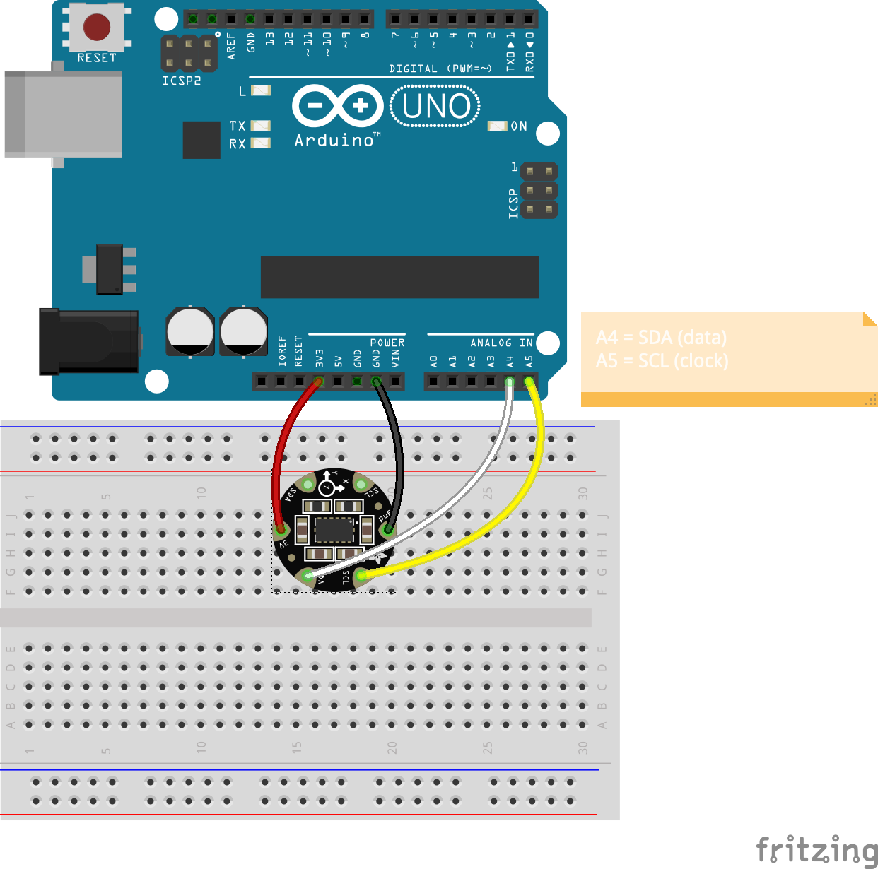
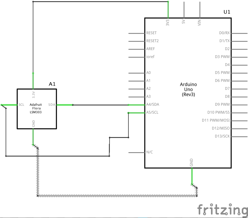
The sensor has a digital (I2C) interface for communication so you need to connect the sensor’s SCL/SDA pins to the SCL/SDA pins on your Arduino (A4/A5 on the Arduino Uno/Uno Wifi and Nano 33 IoT) for proper asynchronous serial communication. It requires 3.3V for power (your Arduino should have a 3.3V output). Let’s use the LSM303 to calculate Roll, Pitch & Yaw and use that data to rotate a 3D object in Processing along three axes.
Steps and observations:
- Build the circuit below.
- Upload the Arduino code below to your Arduino.
- Create a new sketch in Processing and copy the Processing code below in it.
- Pick up your LSM303, Arduino and breadboard and move/rotate them.
- Observe the 3-D object move and rotate in response.
/*
 * Example of using Arduino and Adafruit LSM303 Accelerometer to determine tilt
 *
 *
 * Carlos Castellanos
 * August 24, 2020
 *
 */


#include <Adafruit_LSM303_Accel.h>
#include <Adafruit_Sensor.h>
#include <Wire.h>

/* Assign a unique ID to this sensor at the same time */
Adafruit_LSM303_Accel_Unified accel = Adafruit_LSM303_Accel_Unified(54321);


void setup(void) {
#ifndef ESP8266
  while (!Serial)
    ; // will pause Zero, Leonardo, etc until serial console opens
#endif
  Serial.begin(9600);
  Serial.println("Adafruit LSM303 Accelerometer Test");
  Serial.println("");

  /* Initialise the sensor */
  if (!accel.begin()) {
    /* There was a problem detecting the ADXL345 ... check your connections */
    Serial.println("Ooops, no LSM303 detected ... Check your wiring!");
    while (1)
      ;
  }

  /* Display some basic information on this sensor */
  displaySensorDetails();

  accel.setRange(LSM303_RANGE_4G);
  Serial.print("Range set to: ");
  lsm303_accel_range_t new_range = accel.getRange();
  switch (new_range) {
  case LSM303_RANGE_2G:
    Serial.println("+- 2G");
    break;
  case LSM303_RANGE_4G:
    Serial.println("+- 4G");
    break;
  case LSM303_RANGE_8G:
    Serial.println("+- 8G");
    break;
  case LSM303_RANGE_16G:
    Serial.println("+- 16G");
    break;
  }

  accel.setMode(LSM303_MODE_NORMAL);
  Serial.print("Mode set to: ");
  lsm303_accel_mode_t new_mode = accel.getMode();
  switch (new_mode) {
  case LSM303_MODE_NORMAL:
    Serial.println("Normal");
    break;
  case LSM303_MODE_LOW_POWER:
    Serial.println("Low Power");
    break;
  case LSM303_MODE_HIGH_RESOLUTION:
    Serial.println("High Resolution");
    break;
  }
}

void loop(void) {
  /* Get a new sensor event */
  sensors_event_t event;
  accel.getEvent(&event);

  /* send the results for orientation over the serial port */
  Serial.print(event.orientation.roll);
  Serial.print(",");
  Serial.print(event.orientation.pitch);
  Serial.print(",");
  Serial.println(event.orientation.heading);

  /* short delay to keep things stable */
  delay(1);
}

void displaySensorDetails(void) {
  sensor_t sensor;
  accel.getSensor(&sensor);
  Serial.println("------------------------------------");
  Serial.print("Sensor:       ");
  Serial.println(sensor.name);
  Serial.print("Driver Ver:   ");
  Serial.println(sensor.version);
  Serial.print("Unique ID:    ");
  Serial.println(sensor.sensor_id);
  Serial.print("Max Value:    ");
  Serial.print(sensor.max_value);
  Serial.println(" m/s^2");
  Serial.print("Min Value:    ");
  Serial.print(sensor.min_value);
  Serial.println(" m/s^2");
  Serial.print("Resolution:   ");
  Serial.print(sensor.resolution);
  Serial.println(" m/s^2");
  Serial.println("------------------------------------");
  Serial.println("");
  delay(500);
}
/*

=================================================
==  Arduino and Adafruit LSM303 Accelerometer  ==
==  3D Tilt example                            ==
==                                             ==
==  Carlos Castellanos                         ==
==  August 24, 2020                            ==
=================================================

*/

import processing.serial.*;

Serial myPort;

PShape myShape;

float roll, pitch, yaw;

void setup() {
  size (800, 800, P3D);

  // load the 3d model
  myShape = loadShape("07-14-15.obj");

  // Change the number in the Serial.list() array to the appropriate
  // number of the serial port that your microcontroller is attached to.
  String portName = Serial.list()[2];
  myPort = new Serial(this, portName, 9600);
  // empty the serial buffer
  myPort.clear();
  // don't generate a serialEvent() until you get an ASCII newline character
  myPort.bufferUntil('\n');
}

void draw() {
  background(0);

  // Set a new co-ordinate space
  pushMatrix();

    // add some 3 point lighting
    pointLight(200, 108, 0,  400, 400,  500);
    pointLight(200, 200, 255, -400, 400,  500);
    pointLight(255, 255, 255,    0,   0, -500);

    // Displace objects from 0,0
    translate(width/2, height/2, 0);

    textSize(18);
    fill(204);
    text("degrees     roll: " + roll + "          pitch: " + pitch + "          yaw: " + yaw, -320, 340);

    // rotate the model (convert degrees to radians first)
    rotateX(radians(roll));
    rotateY(radians(pitch));
    rotateZ(radians(yaw));

    pushMatrix();
      noStroke();
      // 3D 0bject
      shape(myShape, 0, 0);
      //box(100, 100, 100);
    popMatrix();
  popMatrix();
}

// Read data from the Serial Port
void serialEvent (Serial myPort) {
  // read the data from the Serial Port up to the newline character
  String data = myPort.readStringUntil('\n');

  // if you get any bytes other than the linefeed
  if (data != null) {
    data = trim(data); // remove whitespace characters
    // split the string at the commas and convert to floats
    float items[] = float(split(data, ','));
    // now print out those three floats using a for() loop
    print("Roll/Pitch/Yaw = ");
    for(int i=0; i<items.length; i++) {
      print(items[i] + "/t");
    }
    // add a linefeed at the end
    println();

    // assign the sensor tilt values (in degrees)
    if (items.length > 1) {
      roll = items[0];
      pitch = items[1];
      yaw = items[2];
    }
  }
}
Notes:
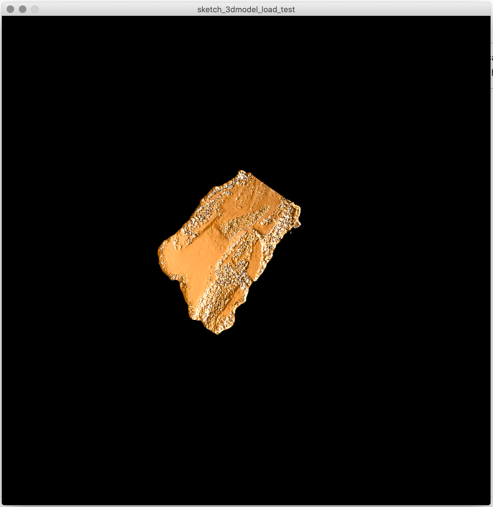
The Processing sketch loads a 3D model (an OBJ file). You can get that file (as well as the Processing code here. The sketch should look something like this:
The Arduino code, schematic and breadboard layout is available here.
Working with the Built-in Accelerometer and Gyroscope on the Arduino Nano 33 IoT
Most built-in IMUs come with a board-specific library. The Nano 33 IoT uses the Arduino_LSM6DS3 library.
The LSM6DS3 IMU that’s on the Nano 33 IoT contains an accelerometer and gyroscope. The IMU is built into the board, so there is no additional circuitry needed. The code example below will read the accelerometer and return the “raw” acceleration in g’s and send the data out through the serial port.
/*
  Arduino LSM6DS3 - Simple Accelerometer

  This example reads the acceleration values from the LSM6DS3
  sensor and continuously prints them to the Serial Monitor
  or Serial Plotter.

  The circuit:
  - Arduino Uno WiFi Rev 2 or Arduino Nano 33 IoT

  created 10 Jul 2019
  by Riccardo Rizzo (modified by Carlos Castellanos (2023)

  This example code is in the public domain.
*/

#include <Arduino_LSM6DS3.h>

void setup() {
  Serial.begin(9600);
  while (!Serial);

  if (!IMU.begin()) {
    Serial.println("Failed to initialize IMU!");

    while (1);
  }

  Serial.print("Accelerometer sample rate = ");
  Serial.print(IMU.accelerationSampleRate());
  Serial.println(" Hz");
  Serial.println();
  Serial.println("Acceleration in g's");
  Serial.println("X\tY\tZ");
}

void loop() {
  float x, y, z;

  if (IMU.accelerationAvailable()) {
    IMU.readAcceleration(x, y, z);

    Serial.print(x);
    Serial.print(',');
    Serial.print(y);
    Serial.print(',');
    Serial.println(z);

  /* short delay to keep things stable */
  delay(1);
  }
}
Measuring Roll, Pitch & Yaw With the Arduino 33 IoT
While accelerometers can measure acceleration of an object, gyroscopes can measure angular velocity (rotation). Using both of these together we can determine the orientation (roll, pitch and yaw) of an object.
As mentioned above, determining orientation from an IMU takes some advanced math. Fortunately, there are a few algorithms that take care of this for us. The MadgwickAHRS by Sebastian Madgwick is a very efficient set of algorithms for determining roll, pitch and yaw using data from IMU sensors. The MadgwickAHRS library for Arduino, by Helena Bisby (and improved upon by Paul Stoffregen and members of the Arduino staff) works with just about any IMU as long as you know the IMU’s sample rate and sensitivity ranges. Here’s an example that uses the MadgwickAHRS library and the Nano 33 IoT’s LSM6DS3 IMU to determine roll, pitch and yaw:
#include <Arduino_LSM6DS3.h>
#include <MadgwickAHRS.h>


// initialize a Madgwick filter:
Madgwick madgwick;
// sensor's sample rate is fixed at 104 Hz
// you can also get this info by calling accelerationSampleRate() or gyroscopeSampleRate()
const float sensorRate = 104.00;

void setup() {
  Serial.begin(9600);
  // attempt to start the IMU:
  if (!IMU.begin()) {
    Serial.println("Failed to initialize IMU");
    // stop here if you can't access the IMU:
    while (true);
  }
  // start the filter to run at the sample rate:
  madgwick.begin(sensorRate);
}

void loop() {
  // values for acceleration and rotation:
  float xAcc, yAcc, zAcc;
  float xGyro, yGyro, zGyro;

  // values for orientation:
  float roll, pitch, yaw;
  // check if the IMU is ready to read:
  if (IMU.accelerationAvailable() && IMU.gyroscopeAvailable()) {
    // read accelerometer &and gyrometer:
    IMU.readAcceleration(xAcc, yAcc, zAcc);
    IMU.readGyroscope(xGyro, yGyro, zGyro);

    // update the filter, which computes orientation:
    madgwick.updateIMU(xGyro, yGyro, zGyro, xAcc, yAcc, zAcc);

    // print the heading, pitch and roll
    roll = madgwick.getRoll();
    pitch = madgwick.getPitch();
    yaw = madgwick.getYaw();
    Serial.print(roll);
    Serial.print(",");
    Serial.print(pitch);
    Serial.print(",");
    Serial.println(yaw);

    // short delay to keep things stable
    delay(1);
  }
}
After uploading this code to your board, try running the Processing sketch above. You can also get both scripts here:
- Processing (make sure you download the OBJ file as well)
- Arduino
Further Reading
Getting Started With the Flora Accelerometer
Accessing Accelerometer Data on Nano 33 IoT
Accessing Gyroscope Data on Nano 33 IoT
Wikipedia article for Accelerometer