Introduction
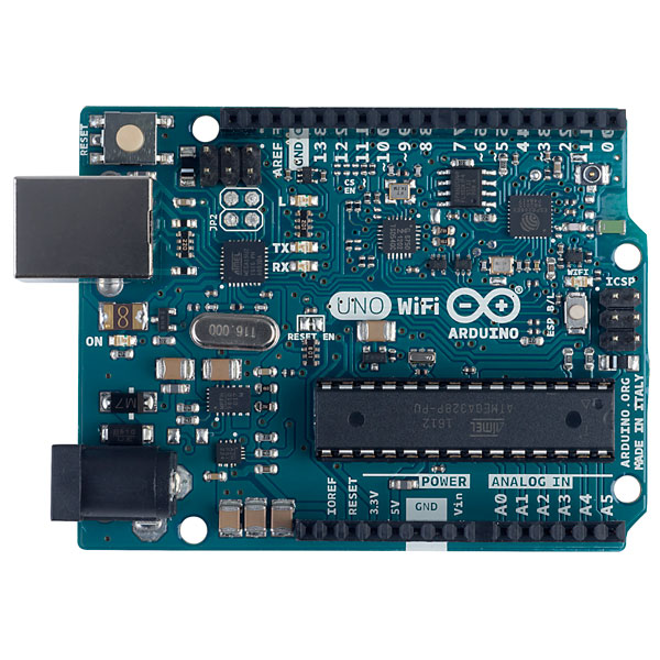
This lab activity introduces logic IC chips and their use in physical computing and Arduino projects. We will be using logic ICs from the 7400 and 4000 series. Many of these chips are built using CMOS (complimentary metal oxide semiconductor) technology and thus they are often referred to as CMOS logic ICs. These are very common, well-known chips used in all kinds of applications. Here we will be using them to expand the I/O capacity of your Arduino. There are times when you may run out of pins on your Arduino board. In this lab we will see examples of using a shift register and an analog multiplexer/demultiplexer to expand the in and outputs on your Arduino board.
What You Will Need to Know
To get the most out of this lab, you should be familiar with the following concepts beforehand. If you’re not, review the links below:
Items You Will Need
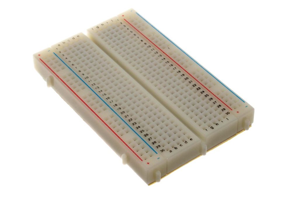
Breadboard 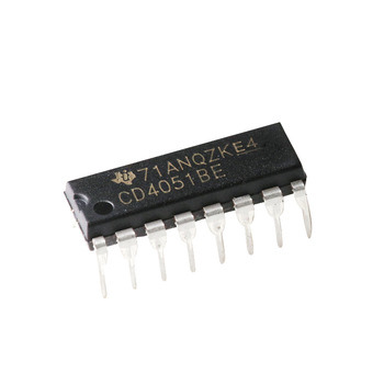
4051 multiplexer/demultiplexer 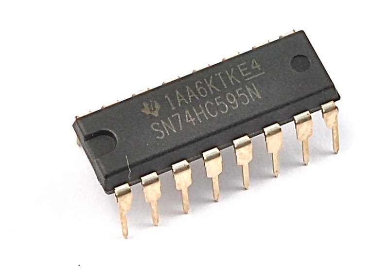
74HC595 shift register 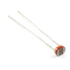
Photocells (x8) 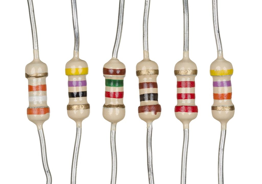
Resistors (560ohm) (x8) & 10k (x8) 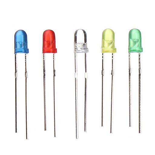
LEDs (x8) 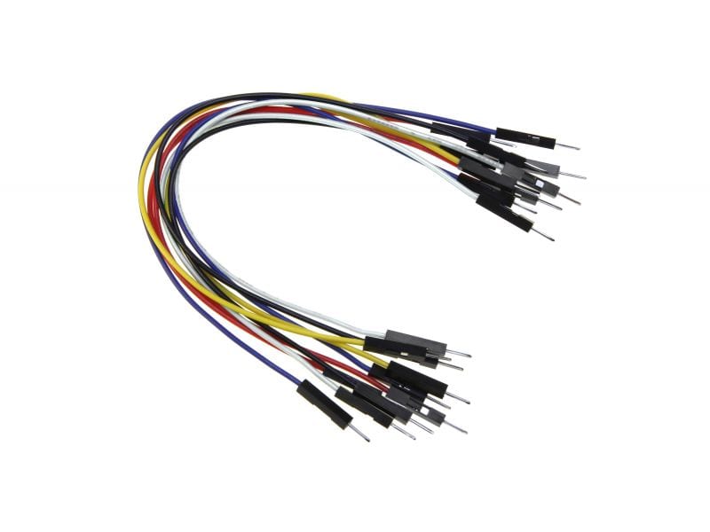
Jumper wires 
Capacitor (0.1uF or similar) (optional)
All of the relevant files for this lab activity can be found here.
Overview of 4051 Multiplexer/Demultiplexer
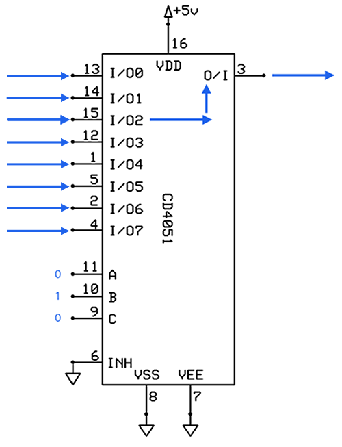
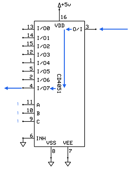
The 4051 (and its functional equivalent, the 74×4051) is a 1-of-8 analog multiplexer/demultiplexer (also known as a 1-of-8 switch). Multiplexing means multiple inputs to one output; choosing from one of various lines (one at a time) and forwarding the contents down a single line. Demultiplexing is doing the reverse, one input to multiple outputs; a single input line is forwarded to one of many output lines.
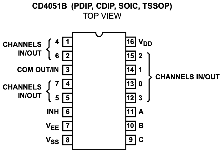
Note: A is the low-order bit. So therefore if you set A and B high, and C low, you would activate channel 3, not channel 6.
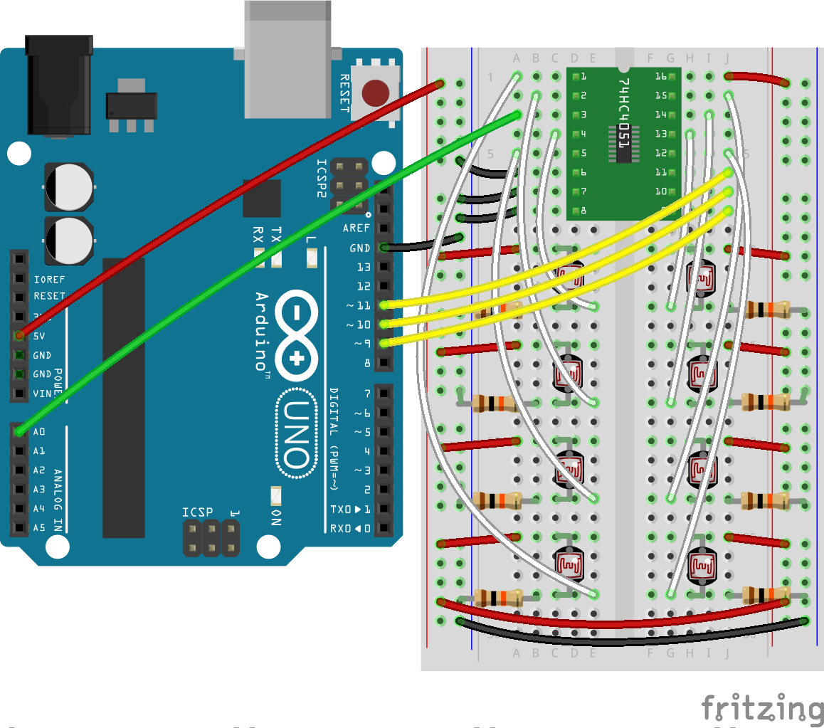
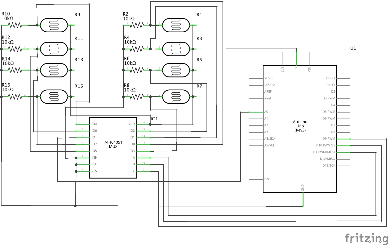
Reading Eight Photocells on a Single Analog Input
We are going to use the 4051 as a multiplexer to take readings from eight photocells on a single Arduino analog input.
Steps and observations:
- Build the circuit below.
- Upload the code below to your Arduino.
- Select the Serial Monitor and observe the changes in distance as you move an object (or your finger) closer and further away from each sensor.
- Experiment by changing the angle of the object (or finger) with respect to each sensor.
/*
 * Example of using the 4051 (74HC4051) multiplexer/demultiplexer
 *
 *
 * Carlos Castellanos
 * August 19, 2020
 *
 * Based on code by Nick Gammon
 * http://www.gammon.com.au/forum/?id=11976
 *
 */


/***********************
=== PIN DEFINITIONS ===
***********************/
//where  the multiplexer address select lines (A/B/C) (pins 11/10/9 on the 4051) are connected
const byte addressA = 11; // low-order bit
const byte addressB = 10;
const byte addressC = 9;  // high-order bit

// where the multiplexer common in/out line (pin 3 on the 4051) is connected
const byte sensor = A0;


void setup (){
  Serial.begin (9600);
  Serial.println ("Starting multiplexer test ...");
  pinMode (addressA, OUTPUT);
  pinMode (addressB, OUTPUT);
  pinMode (addressC, OUTPUT);
}

void loop () {
  // show all 8 sensor readings
  for(byte i=0; i<=7; i++) {
    Serial.print("Sensor ");
    Serial.print(i);
    Serial.print(": ");
    Serial.println(readSensor(i));
    Serial.println();
  }
  delay(500);
}

int readSensor (const byte which) {
  // select correct MUX channel

  // low-order bit
  if((which & 1)) {
    digitalWrite(addressA, HIGH);
  } else {
    digitalWrite(addressA, LOW);
  }

  if((which & 2)) {
    digitalWrite(addressB, HIGH);
  } else {
    digitalWrite(addressB, LOW);
  }

  // high-order bit
  if((which & 4)) {
    digitalWrite(addressC, HIGH);
  } else {
    digitalWrite(addressC, LOW);
  }

  /* a more efficient (if slightly abstruse) way of doing the above
  digitalWrite (addressA, (which & 1) ? HIGH : LOW);  // low-order bit
  digitalWrite (addressB, (which & 2) ? HIGH : LOW);
  digitalWrite (addressC, (which & 4) ? HIGH : LOW);  // high-order bit
  */

  // now read the sensor
  return analogRead(sensor);
}
Notes:
Remember that changing the value of the fixed resistor changes the range of values the sensor will give you, effectively altering its sensitivity. If you think of these eight sensors as one device topologically, you can alter its responsiveness, its “feel”, by making some areas more sensitive than others.
Overview of the 74HC595 Shift Register
The 74HC595 is an is an 8-stage serial shift register or serial-to-parallel converter. This means that you can use it to control 8 outputs at a time with just three pins of an Arduino. The best way to think about this chip is that it is a physical byte of data, where you can control the state of each bit electronically. To set the 8 bits on/off we feed in the data using the ‘Data’ and ‘Clock’ pins of the chip. The clock pin needs to receive eight pulses. At each Clock pulse, if the Data pin is high, then a 1 gets pushed into the shift register. Otherwise, a 0 gets pushed. When eight clock pulses have been received, this enables the ‘Latch’ pin and copies the eight values (the whole byte) to the latch register (also known as the storage register). When the value in this register changes, so do the outputs (this is the parallel output). It needs to be done this way (as opposed to one bit out at a time), because otherwise the wrong LEDs would flicker as the data was being loaded into the shift register. This shift register works in a manner very similar to synchronous serial communication, as the data transmission is synced to a clock pulse. The below animation should help explain.
Below is a table explaining the pin-outs on the 74HC595. For more details, refer to the datasheet.
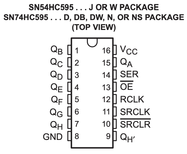 | PIN NUMBER | FUNCTION NAME | DESCRIPTION |
| PINS 1-7, 15 | QA-QH | Output Pins | |
| PIN 8 | GND | Ground | |
| PIN 9 | QH´ | Serial Out | |
| PIN 10 | SRCLR | Shift Register Clear (active LOW) | |
| PIN 11 | SRCLK | Shift Register Clock (Clock pin) | |
| PIN 12 | RCLK | Storage Register Clock (Latch pin) | |
| PIN 13 | OE | Output Enable (active LOW) | |
| PIN 14 | SER | Serial Input (Data pin) | |
| PIN 16 | VCC | Positive supply voltage |
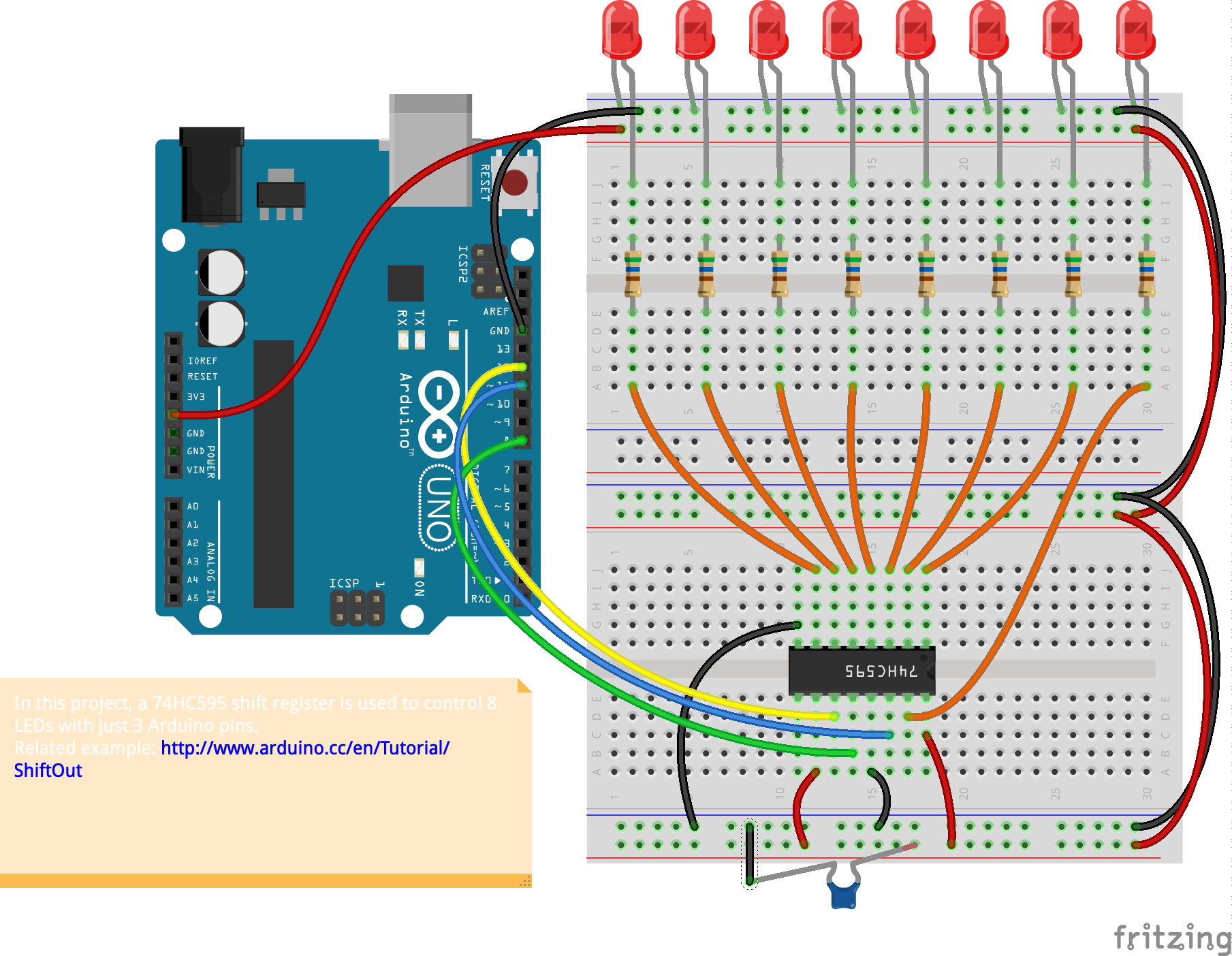
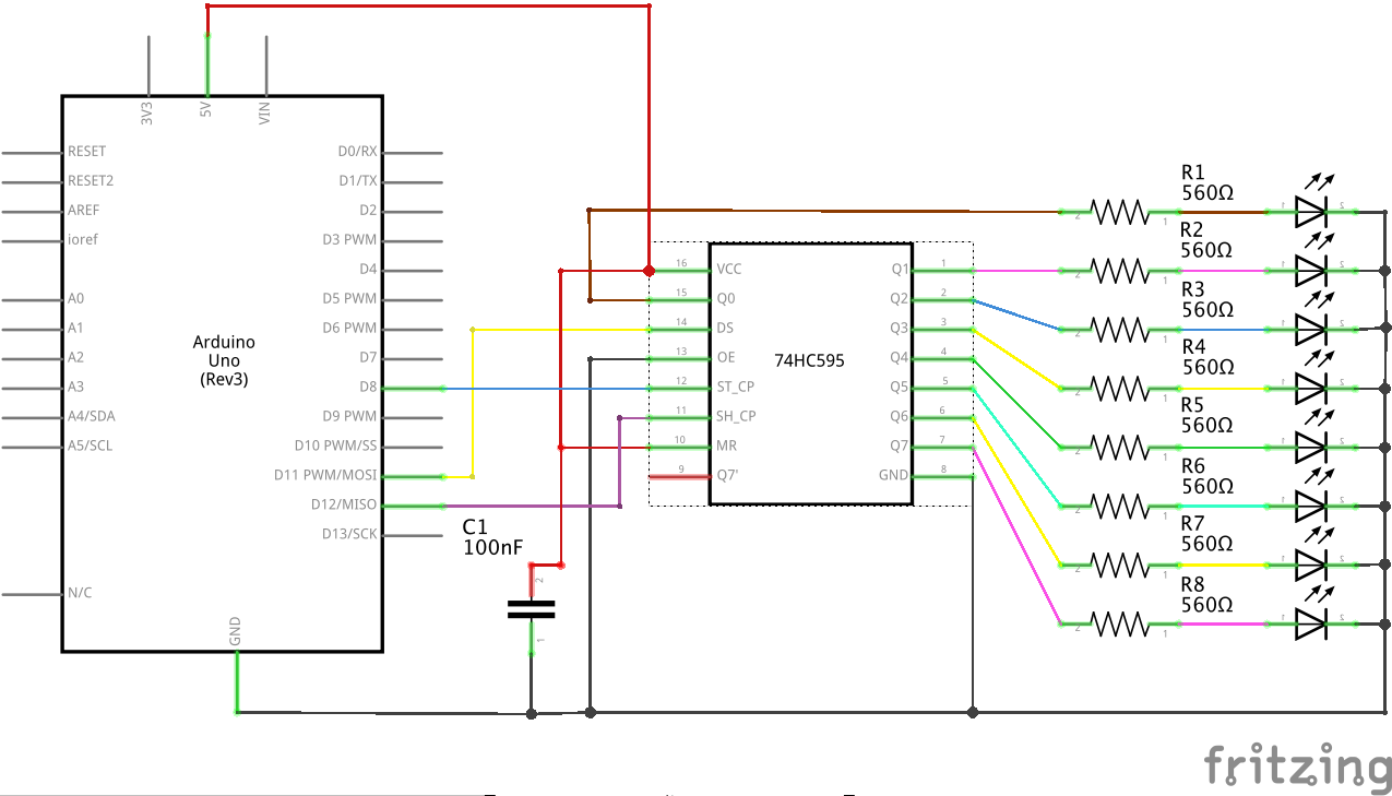
Control Eight LEDs With Three Arduino Pins
We will be using the 74HC595, to control eight LEDs from three Arduino digital pins.
Steps and observations:
- Build the circuit below.
- Upload the code below to your Arduino.
- Observe the LEDs light up in a sequence (they should light up one at time and then turn off after all eight have turned on; the cycle then repeats)
- Alter the code to create a different sequence pattern.
/*
 * Shift Register Example for 74HC595 shift register
 *
 * Carlos Castellanos
 * August 20, 2020
 *
 */


/***********************
=== PIN DEFINITIONS ===
***********************/
// Arduino pin connected to latch pin (RCLK) of 74HC595
const int latchPin = 8;
// Arduino pin connected to clock pin (SRCLK) of 74HC595
const int clockPin = 12;
// Arduino pin connected to the serial input pin (SER) of 74HC595
const int dataPin = 11;

// an array of bytes (in binary) representing an LED on/off sequence
const byte seq[8] = {B00000001, B00000011, B00000111, B00001111, B00011111, B00111111, B0111111, B11111111};

const int seqDelay = 400;   // delay between each full sequence
const int stepDelay = 100;  // delay between each sequence step

void setup() {
  // set pins to output because they are addressed in the main loop
  pinMode(latchPin, OUTPUT);
  pinMode(dataPin, OUTPUT);
  pinMode(clockPin, OUTPUT);
}

void loop() {
  updateShiftRegister(0);         // turn off all LEDs
  delay(seqDelay);
  for(int i=0; i<8; i++) {
    updateShiftRegister(seq[i]);  // loop through the seq array and update the shift register
  }
}

void updateShiftRegister(byte b) {
  digitalWrite(latchPin, LOW);              // pull latch LOW to start sending data into the memory register
  shiftOut(dataPin, clockPin, LSBFIRST, b); // send the data
  digitalWrite(latchPin, HIGH);             // pull latch HIGH to copy values to the latch register and send out
  delay(stepDelay);
}
Notes:
The 100nF (0.1uF) capacitor (C1) between VCC and ground is an optional decoupling capacitor.
If you read the datasheet for the 74HC595 you will see that the chip can supply a maximum of 70mA of continuous current. This means we have to be a little bit careful with the resistor value we put in front of each LED. LEDs (indeed all diodes) have a characteristic known as a “forward voltage”. This refers to the amount of voltage “lost” in the LED when it is operated at a certain reference current (usually defined to be about 20 mA). This forward voltage actually varies depending on the color of the LED (red LEDs have about 1.8-2.2V forward voltage, while green LEDs have about 2.5-3V voltage drop; as these numbers can vary, it’s a good idea to check the datasheet). All this is to say that we need to make sure we limit the current enough so as to not stress the 74HC595 too much. If we have +5V supply and we use 560 ohm resistors, that should give us about 5mA per red LED and 3.4mA per green, which should be enough to light all eight of them nicely without overloading our chip. Anything less than 390 ohms is not recommended. If you are using a 3.3V supply, 220 ohm resistors will work just fine. More information on forward voltage and current limiting resistors for LEDs is available here.
Further Reading
CMOS Cookbook, Dan Lancaster
Nick Gammon’s multiplexer / demultiplexer tutorial
Arduino Playground Analog Multiplexer/Demultiplexer tutorial
Adafruit shift register tutorial
How 74HC595 Shift Register Works & Interface it with Arduino
74HC595 shift register datasheet
List of 4000-series integrated circuits