Introduction
This lab is an introduction to some of the components you will use when making electronic circuits. There are no specific activities in this lab other than to examine the components and familiarize yourself with them. For more on any given component, please check out its datasheet. This is a document that describes the technical characteristics of a particular component, sensors, device, material, etc. It includes details on how to use the it, its configuration and its limitations (e.g. how much current it can take and/or produce). Specifications on performance and other characteristics that are important to know are also typically included.
Components
Resistors
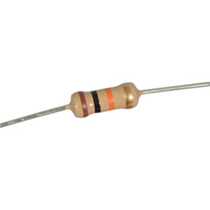
Resistors (as the name implies) resist the flow of electrical current (and thus reduce the voltage as well). Resistance is measured in ohms, the symbol for ohm is Ω (omega). When resistors are connected in series their combined resistance increases. When connected in parallel their combined resistance is reduced.
The bands on a resistor indicate the resistor’s value. Resistors come in 4-band, 5-band, and 6-band models. In a 4-band resistor (the type you will encounter most often), the bands represent the first digit, second digit, multiplier, and tolerance. The resistor shown in Figure 1 is 4-band 10KΩ resistor marked brown, black, orange, and gold, for 1, 0, times 103, 5%. In other words, it is a 10,000 ohm resistor, +/-5%. The 5 and 6-band variety are basically the same, just more accurate (6-band resistors even include a temperature coefficient band). You may want to try this handy resistor color code calculator. Or you can refer to the image below.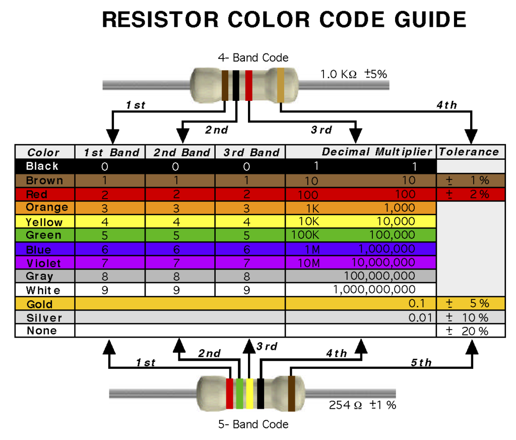
LEDs
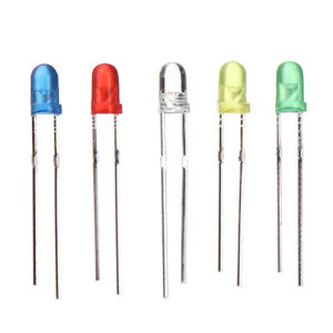
LED’s (Light Emitting Diodes) are components that emit light when current flows through them. LEDs are polarized, meaning that they only operate when oriented correctly in the circuit. The anode of the LED (the longer leg) connects to voltage, and the cathode (shorter leg and flattened edge of plastic casing/lens) connects to ground. LEDs are cheap but not not very bright. You can get super-bright LEDs which (as the name implies) are much brighter. LEDs come in many different packages. The LEDs shown in Figure 2 have built-in lenses/casings in multiple colors (note: the color of an LED is actually determined by its semiconductor material, not by the color of the casing).
LEDs are different from other light sources (such as lamps) and must be protected from passing too much current. This is is achieved by connecting a resistor in series with the LED. Never connect an LED directly to a battery or power supply. For most common LEDs running at 3.3 or 5 volts, a resistor about 220-1KΩ will limit the current safely while still providing enough to light the LED.
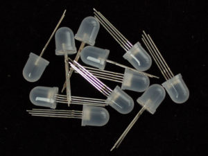
If you want an LED that produces more than one color and RGB LED is a good candidate. As you can see in Figure 3, RGB LEDs have four legs instead of two. Three of the legs are for red, green and blue and the fourth is either an anode or cathode (depending on where it is a common-anode or common-cathode LED). Each color can be switched on and off separately allowing a range of colors to be produced.
If you need multiple LEDs, an LED strip is the probably best way to go. These devices typically contain many small surface mounted super-bright LEDs (either single color or RGB) and can be controlled via a microcontroller to all kinds of cool patterns, colors, etc.. These strips require their own power power supply to run. Adafruit Neopixels and Dotstars are two very good, well-supported LED strip products.
Capacitors
Capacitors store electrical energy while there’s energy coming in, and release it when the incoming energy stops. There are many types of capacitors. Some are polarized, some non-polarized. The three most common are shown below. Capacitance is measured in farads, with the symbol F. However, 1F is very large so prefixes (multipliers) are used to show smaller values:
- µ (micro) means 10-6 (millionth), so 1000000µF = 1F
- n (nano) means 10-9 (thousand-millionth), so 1000nF = 1µF
- p (pico) means 10-12 (million-millionth), so 1000pF = 1nF
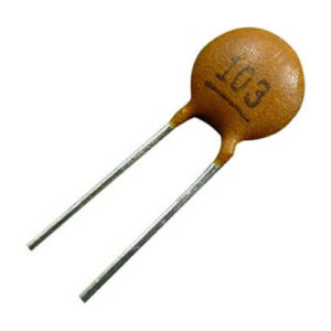
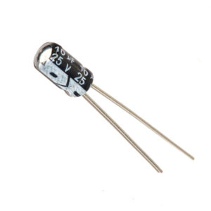
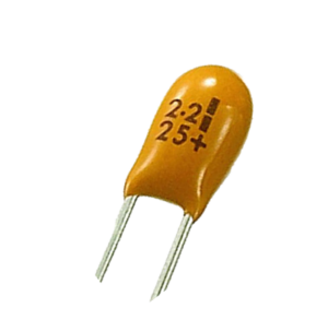
Capacitors have a variety of uses. They can be used to create oscillators, filters, sensors and much more. One common use is to smooth out the dips and spikes in an electrical supply. This use is called decoupling. Ceramic capacitors (Figure 4) are unpolarized. They generally have very small capacitance values. Electrolytic capacitors (Figure 5) generally store more charge than ceramics, and are longer lasting. They’re usually polarized, meaning that they have a positive leg and a negative leg. Tantalum capacitors (Figure 6) are a subset of electrolytics and typically have a higher capacitance value per volume.
Potentiometers
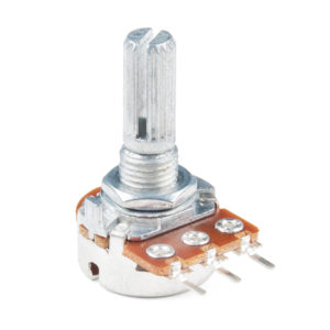
Potentiometers are variable resistors. The two outside terminals make up the resistance track, acting as a fixed resistor. In the middle is a movable contact called the wiper that moves across the resistance track as you turn the spindle. This produces a variable resistance between the center terminal and either of the two sides. Potentiometers can be linear or logarithmic taper. Linear that the resistance changes at a constant rate as you move the wiper, whereas logarithmic taper means that the resistance changes slowly at one end of the track and rapidly at the other (so halfway along the track is not half the total resistance!). Linear taper is used for most applications while logarithmic taper is often used for audio applications (and in fact is sometimes called audio taper), since the human ear has a logarithmic response to loudness. Figure 7 shows a standard rotary potentiometer.
Photocells
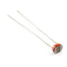
Photocells (also known as light-dependent resistors or photoresistors), are variable resistors whose resistance changes (usually decreases) with exposure to light (more light intensity = less resistance). A typical photocell is shown in in Figure 8.
Switches
Switches are perhaps the most basic type of digital input. There are many kinds of switches but they can be placed into two basic categories: momentary (or biased) switches, which remain closed only when you press them, and toggle (or unbiased) switches, which stay in place after you switch them.
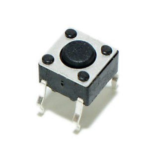
Pushbuttons are a common type of momentary switch. The momentary pushbutton shown in Figure 9 can be mounted on a circuit board or breadboard. They switches are typically very small, usually less than 1 centimeter on a side. They have four pins. When the button is facing you, top two are connected to each other, and the bottom two are connected to each other. Pushing the button connects the top pins to the bottom pins.
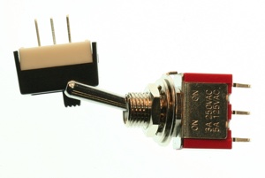
Toggle switches (Figure 10) stay in one position when you flip them. Toggle switches usually have two or three connectors (or positions) (although they can have more). On a 3-position toggle, the connections are typically labeled C for common, NO for Normally Open, and NC for Normally Closed. When you switch the toggle, it will open the connection between the common pin and the normally closed pin, and close the connection between the common pin and the normally open pin. Switch it the other way and it reverses the connection.
Solderless Breadboards
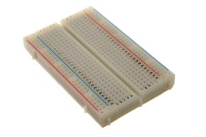
Solderless breadboards (Figure 11) are one of the most fundamental pieces for prototyping and learning how to build circuits. A breadboard contains strips of metal underneath the board that contain internally connected rows and columns. There is a divider down the center of the board that breaks up the rows of holes into separate rows. There are five holes per row on the center left and on the center right of each row. Breadboards allow you to build and experiment with temporary circuits simply by plugging components in and out of these rows and columns.
Diodes
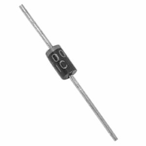
Diodes (Figure 12) are components that allow current to flow in only one direction (and block it in the other direction). As you might expect, diodes are polarized devices, with the cathode indicated by a band painted on the body. Zener diodes are a special kind of diode that actually allow reverse current after the “breakdown voltage” is reached. Diodes are useful in many applications. Most common are reverse voltage protection, power supplies, voltage regulators and AC to DC conversion.
Transistors
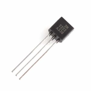
Transistors (Figure 13) function as electronic switches or amplifiers. Basically you can control or turn on/off a high current/voltage with a low one (e.g. from a digital pin on your Arduino). When a small voltage is put to one of the pins (the “base” or “gate” depending on the type of transistor), it allows a larger current and voltage to flow from the “collector” (or “drain”) to the “emitter” (or “source”). Transistors are used in many kinds of circuits such as digital logic and controlling high-current loads like motors.
DC Power Jacks
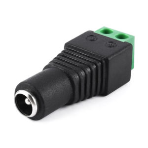
DC Power jacks are used to connect your breadboard to a DC power supply that you can plug into a wall (sometimes called a “wall wart” or “power brick”). They’re very useful for powering high load devices devices like motors or LED strips or anytime you need an additional power supply. The one in Figure 14 has screw terminals on the back to which you can connect wires to connect to your breadboard. It is a 2.1mm inside diameter, 5.5mm outside diameter jack, which is a very common size.
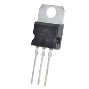
Voltage Regulators
Voltage regulators are integrated circuits (ICs) that take a voltage within a certain range (e.g. 7-18V) and converts it to a constant fixed output voltage (e.g. 5V) regardless of any changes in the load or input voltage (hence the term “regulator”). Different electronic circuits operate at different voltages. Many DC power supplies operate at voltages higher than the electronics which they power. Because different devices require different operating voltages, you often need a voltage regulator to convert from one voltage level to another. Voltage regulators are used in all kinds of devices from cars, to mobile phones to Arduino microcontrollers. A 7805 regulator (as shown in Figure 15) is common regulator used in microntroller projects. It takes voltages from 7-25V (or even more in some versions) and outputs a constant 5V at up to 1.5A.
Piezo Transducers
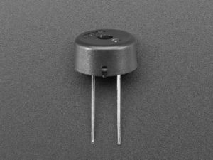
Piezo transducers (Figure 16) convert an electrical signal to sound. They require very little current (usually less than 10mA), and thus can be connected directly to an Arduino digital output pin to make beeps, buzzes and tones. To use one, connect one pin to ground (either one) and the other pin to a square wave out from a timer chip or microcontroller. Piezo transducers can also be used as input transducers for detecting sudden loud noises or impacts, effectively behaving as a crude microphone or vibration sensor.
References
Electronics Club: Components Guide
Identifying Electronic Components (a visual guide)