Introduction
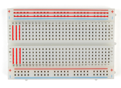
Solderless breadboards are one of the most fundamental pieces of an electronics prototyping toolkit. They are indespensible for learning how to build circuits. Basically, a breadboard is a rectangular plastic board with a bunch of small holes in it. The connections are temporary so it is easy to add or remove a component, or just start over on a new project. The holes are organized in many short rows in the center, and in two long rows down each side. The short horizontal rows in the middle are separated by a center divider. The divider allows you to mount integrated circuit chips, like a microprocessor, since it isolates the two rows from each other. The holes let you easily insert electronic components to prototype and test an electronic circuit without the need for soldering components. This lab shows how to set up a breadboard with an independent power supply (8-12V) through a 5V Voltage Regulator (7805).
What You Will Need to Know
To get the most out of this lab, you should be familiar with the following concepts beforehand. If you’re not, review the links below:
- You should be familiar with electrical components, for example what is a voltage regulator is.
- Batteries and power supplies
Items You Will Need
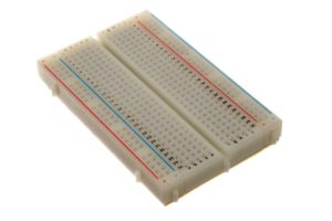
Breadboard 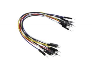
Jumper wires 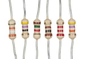
Resistors (220-1K) 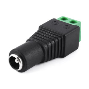
DC power jack – female 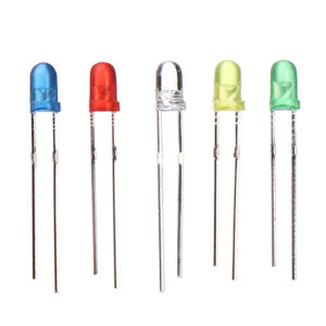
LEDs 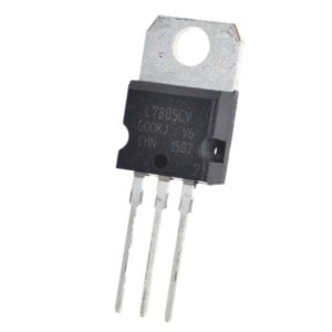
7805 voltage regulator 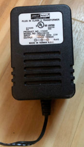
7-15V DC power supply (or 9V battery)
Almost any wall wart power supply will work, as long as it is between 7-15V and has 2.1mm connector (center positive). You can also use a 9V battery with a battery holder like this one from Adafruit.
What’s Inside a Breadboard?
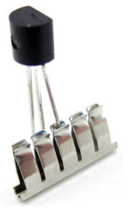
tiny metal clips inside a breadboard 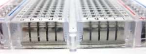
the inside of a breadbaord
The leads from your components can fit into the breadboard because on the inside are of rows of tiny metal clips. This is what the clips look like when they are removed from a breadboard. When you press a component’s lead into a breadboard hole, one of these clips grabs onto it.
Powering the Breadboard
Caution! Avoid adding, removing, or changing components on a breadboard whenever the board is powered. You risk shocking yourself and damaging your components.
In most cases you will bring power into your breadboard via the 5V (or 3.3V) output of your Arduino. However that is not always possible. Plus you need to learn to power things without an Arduino or USB.
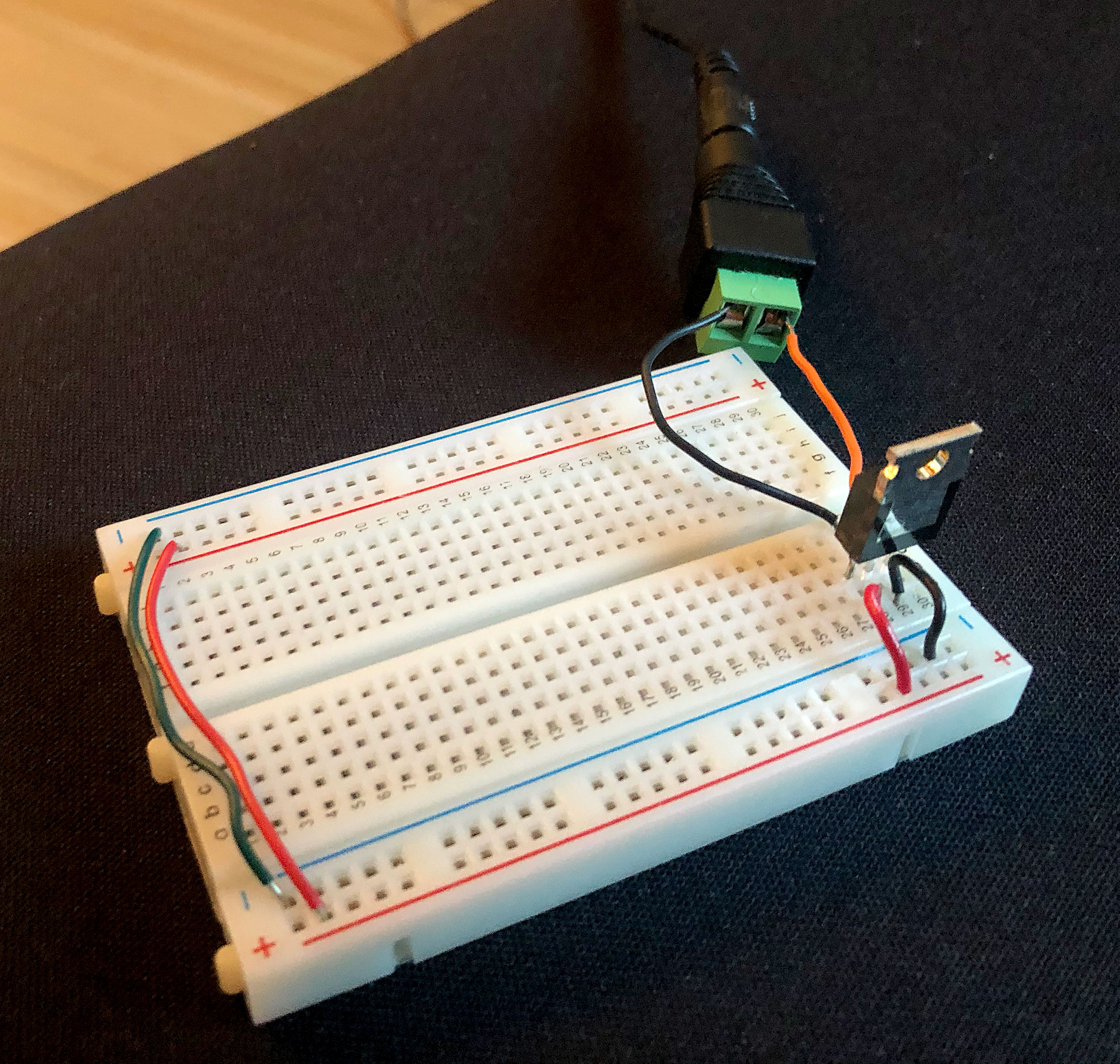
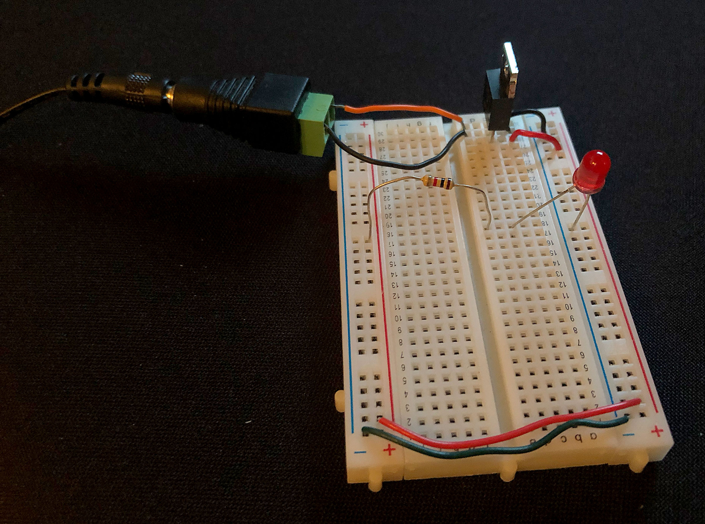
The image below shows a 7805 voltage regulator used to supply +5 Volts DC to the two red side rows of the breadboard. You’re looking at the back of the regulator, so that the pins are, from left to right: voltage out (+5V), ground, voltage in (+7-15V). Notice that the regulator’s voltage out pin on the left is connected to the red row with a wire. The two blue side rows are connected to ground pin of the regulator. These will be your voltage and ground bus rows. They give you lots of convenient places to connect to voltage or ground as needed. You may also notice the black and red wires running from one side of the breadboard to the other. This runs power and ground to both sides of the breadboard, making circuit building easier (as you will see below. Connect everything except the power supply (wall wart or 9V battery).
Now connect an LED and a current limiting resistor (anything between 220-1K will work) in the manner shown below.
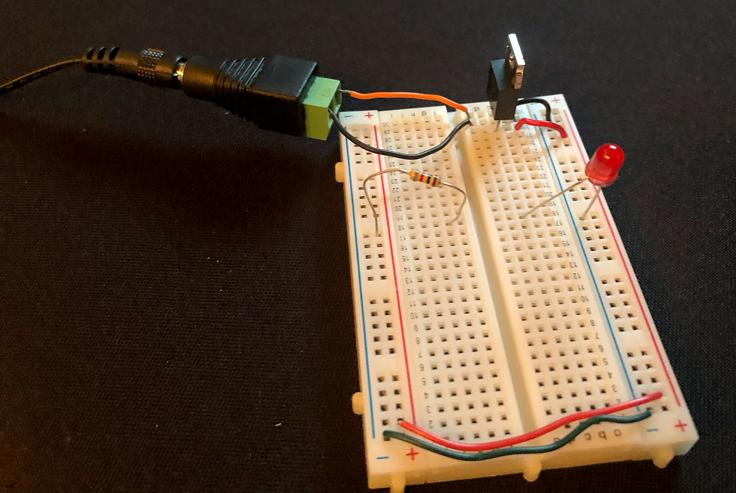
If you plug in the power supply to will the LED light up? No. The reason is that the current flows from the bus row through the resistor to row 18 of the board. The LED’s anode connects to the same row, but on the other side of the center divide, so there is a break in between the resistor and the LED. The LED will not light.
Now take a look at the photo below.
Will the LED light up now? Yes. everything is the same as before except now the resistor connects to the anode of the LED correctly because it is on the other side of the center divide.
Add to the circuit. Instead of fixed resistor, try a potentiometer (the center lead is the one that should be connected to the anode of the LED). Add more LEDs.
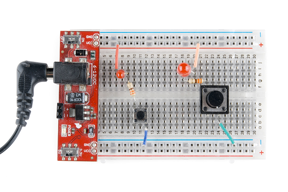
If you are going to be lots of prototyping work that will involve voltage regulators and/or power supplies it might be good idea to get a breadboard power supply like the ones shown below. These fit nice and snug onto one end of your breadboard and provide +5 or 3.3V outputs (switchable or adjustable) and 6-12V inputs. They also typically have on/off switches and reverse polarity protection.
Conclusion
Many options are possible using a breadboard, which is what makes them very useful and convenient for building circuits. Once you understand which holes are connected to each other (and which ones are not), you can build any circuit very quickly. Try to keep your circuits by shortening the wires to only the length you need. Lay things out as sensibly as possible and try to color code your circuits (e.g. red for power, black for ground, etc). That will make troubleshooting much easier.
Further Reading
Sparkfun: How to Use a Breadboard