Introduction
Perhaps the closest thing in the physical world to digital computation is the switch. It is either on or off. Yet even one single physical switch can be used to transition to many states and create complex relationships. Furthermore, any change of state in the physical world (e.g. standing up/sitting down, raising/lowering hand, etc) can be considered a switch in the abstract sense.
In this lab you will connect a digital input circuit and a digital output circuit to your microcontroller. Digital inputs and outputs are the most fundamental physical connections for any microcontroller. These are often called General Purpose Input-Output, or GPIO, pins. Most projects will either use these pins to create or test for binary state transitions or will employ switches in the abstract sense mentioned above.
Breadboard & schematic files for this activity are available from the course code repository on GitHub or can be downloaded from: https://github.com/carloscastellanos/teaching/tree/master/Arduino/Basics/Digital/
Remember to document everything on your blog.
What You Will Need to Know
To get the most out of this lab, you should be familiar with the following concepts beforehand. If you’re not, review the links below:
Items You Will Need
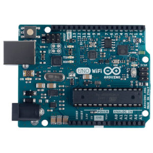
Arduino microcontroller 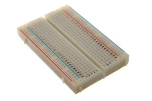
Breadboard 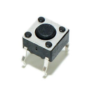
Momentary pushbutton switch 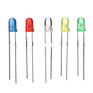
LEDs 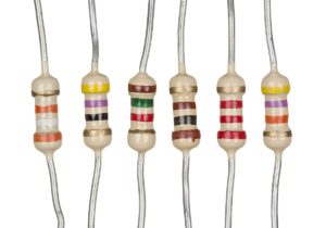
Resistors (560, 1K, 10K) 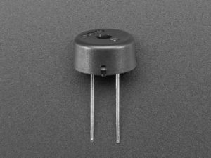
Piezo transducer (optional)
Digital Input and Output
Steps and observations:
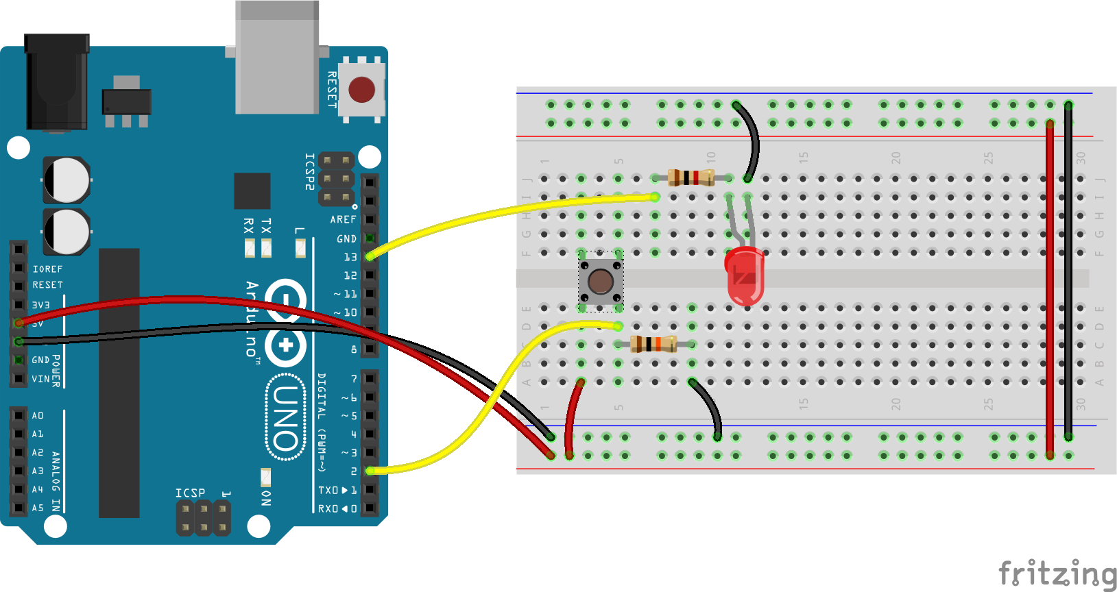
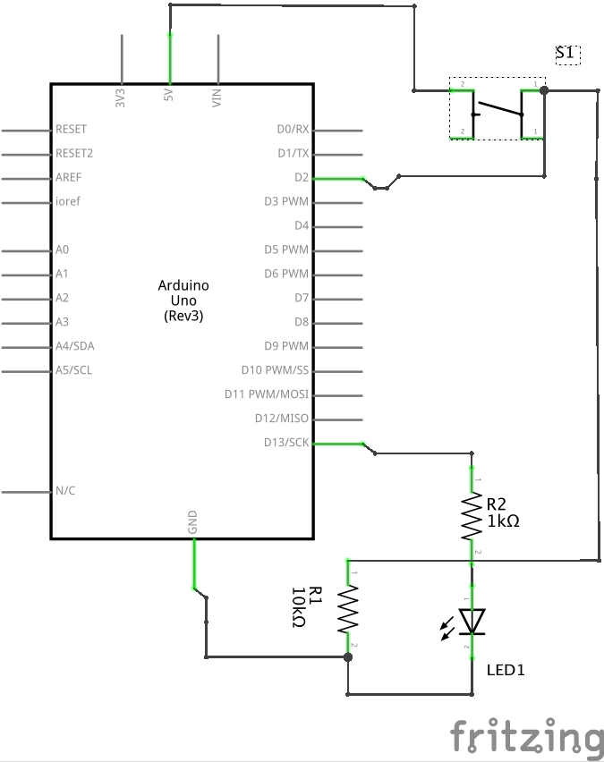
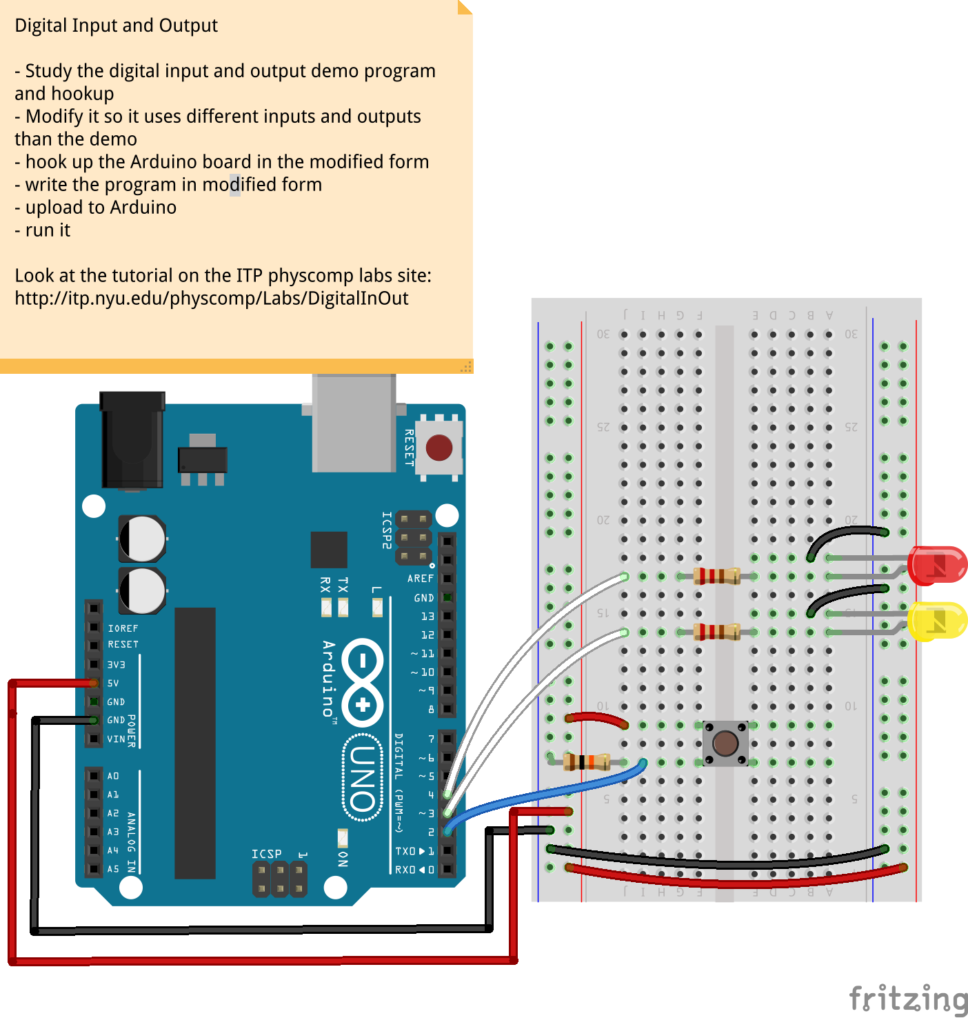
- Build the circuit below (files located in Arduino/Basics/Digital/). If you prefer an audible tone over a blinking LED, you can replace the LED with a piezo transducer/buzzer.
- Open the Button sketch under File->Examples->02.Digital->Button and upload it to your board.
- Press/release the button and observe the LED (or buzzer) turn on/off.
- Troubleshoot if necessary.
- Now experiment with different button pressing/timing patterns. For example, we can change the behavior of the momentary pushbutton from biased to unbiased, meaning press & release to turn on (& stay on) then press and release to turn off (& stay off). See the code below. Experiment with other patterns and behaviors (e.g. double press, press and hold, etc) and map them to different outputs (e.g. double blink, etc). For an even bigger challenge, take a look at the Bonus section at the bottom of this page.
The code below can also be downloaded here.
/*
Button
Carlos Castellanos | 2014 | ccastellanos.com

Press and release to turn an LED on, then press and release again to turn off

Note: this example works best with a momentary pushbutton or similarly biased switch


Schematic, see:
https://github.com/carloscastellanos/teaching/blob/master/Arduino/Basics/Digital/Button_schem.png

Suggestions:
- Can you make the LED go off after a certain amount of time has passed? Hint: while
  using 'delay' will work, you can also look into the 'millis' function...
- add an additional led and/or button na d increase the complexity of behaviors
*/

// constants won't change. They're used here to set pin numbers (faster/saves memory):
const int buttonPin = 2;      // pins for button and LED
const int ledPin = 13;

// store button's status - initialize to OFF (this variable will change, so it's not a const)
int buttonState = 0;
int prevButtonState = 0;
bool on = false;

void setup() {
  pinMode(buttonPin, INPUT);    // set button to input
  pinMode(ledPin, OUTPUT);      // LED to output
}

void loop() {

  // read the state of the button into our variable
  buttonState = digitalRead(buttonPin);

  // test that state
  if (buttonState == HIGH) {      // if button is pressed...
    if(prevButtonState == LOW) {  // if it was previously not pressed
      on = !on;
      digitalWrite(ledPin, on);   // toggle the LED
    }
  }

  prevButtonState = buttonState; // save the previous button state

}
Notes:
The 10K resistor connecting the pushbutton to ground is known as a pulldown resistor. Without pull-up and pulldown resistors, digital inputs would behave unreliably. For more check out the Arduino Digital Pins Tutorial on the Arduino site or Sparkfun’s tutorial on pull-up/pull-down resistors.
If you are using the piezo buzzer, you need to use the tone() and noTone() functions (instead of digitalWrite()).
A digital input is essentially a single-bit analog-to-digital converter, albeit with an ambiguously defined threshold between the voltages representing zero and one (on a 5V Arduino the threshold to go from LOW to HIGH is usually ~2.6V; on a 3.3V Arduino it’s ~1.9V, but check the datasheet(s)).
Multiple Outputs (LEDs)
Steps and observations:
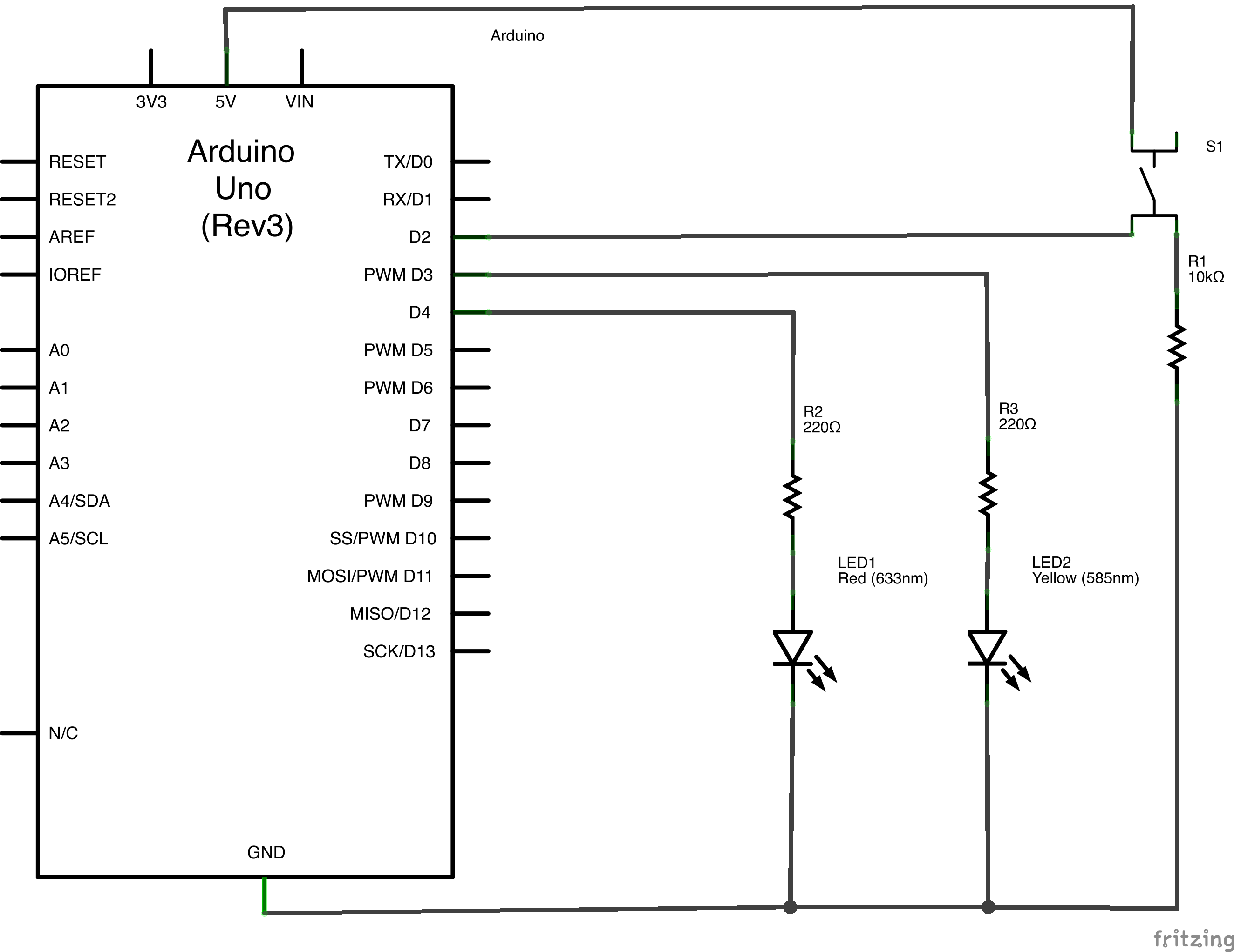
- Build the circuit below (files located in Arduino/Basics/Digital/).
- Now using the previous activity as a guide, write code that will turn the yellow LED on and the red one off when the pushbutton is pressed and turn the red LED on and the yellow LED off when it is released (note: you can use any two colors you like).
- Upload the code to the Arduino and press/release the button to observe the LEDs turn on/off.
- Troubleshoot if necessary.
Bonus
What we’ve been building here are rudimentary finite state machines. Real-world examples of finite state machines include traffic lights, coin-operated turnstiles and game characters with the ability to perform specific actions based on user input (run, jump, throw, etc). We can build simple programs and circuits on the Arduino that can recognize sequential patterns and change their state accordingly. These can be extended to use any binary input: optical switches, temperature thresholds, footsteps, etc. The transition properties can also be extended to include other predicates: comparisons on elapsed time to prevent exiting a state before time has elapsed, more elaborate mappings of linear inputs to transition state.
As a challenge, see if you can create an Arduino program and circuit that recognizes patterns of input. Try to model it on something from your own experience of the world (for example how objects may change or respond based upon how often you touch them, the time in between touches, etc). You can use the code below as a starting point (you will need to devise your own circuit to go with it). The code is also available at: https://github.com/carloscastellanos/teaching/blob/master/Arduino/Basics/Digital/InputMatch.ino
/*
 * Arduino program to demonstrate a simple finite state machine program structure.
 * Carlos Castellanos | 2020 | ccastellanos.com
 *
 * with some code borrowed from Garth Zeglin: https://www.cs.cmu.edu/~garthz/
 *
 * Given the number of outputs, this example could be extended to encompass many more states
 */


const int INPUT_PIN = 4;
const int OUTPUT_PIN_A = 5;
const int OUTPUT_PIN_B = 6;
const int OUTPUT_PIN_C = 7;

// Define the name for each state, and an index variable to represent the
// current state.
enum state_name_t { START=0, STATE1, STATE2, STATE3, STATE4 } state_index;

void setup()
{
  // initialize the Serial port
  Serial.begin(9600);

  // configure our inputs & outputs
  pinMode(INPUT_PIN, INPUT);
  pinMode(OUTPUT_PIN_A, OUTPUT);
  pinMode(OUTPUT_PIN_B, OUTPUT);
  pinMode(OUTPUT_PIN_C, OUTPUT);

  // initialize the state machine
  state_index = START;
}

/****************************************************************/
// Standard Arduino polling function.

// This demonstrates a conventional switch-case structure for representing a
// finite state machine as an Arduino program. The current state is represented
// as the value of the state_index variable. Note that this structure allows
// for easily evaluating other subroutines or state machines concurrently with
// this one, as the execution passes through the loop() function on each
// iteration.

void loop()
{
  // select the code block corresponding to the state to generate the appropriate outputs for the state
  switch( state_index) {

  case START:
    Serial.println("Entering start state.");
    digitalWrite(OUTPUT_PIN_A, LOW);
    digitalWrite(OUTPUT_PIN_B, LOW);
    digitalWrite(OUTPUT_PIN_C, LOW);
    break;

  case STATE1:
    Serial.println("Entering state 1.");
    digitalWrite(OUTPUT_PIN_A, HIGH);
    digitalWrite(OUTPUT_PIN_B, LOW);
    digitalWrite(OUTPUT_PIN_C, LOW);
    break;

  case STATE2:
    Serial.println("Entering state 2.");
    digitalWrite(OUTPUT_PIN_A, LOW);
    digitalWrite(OUTPUT_PIN_B, HIGH);
    digitalWrite(OUTPUT_PIN_C, LOW);
    break;

  case STATE3:
    Serial.println("Entering state 3.");
    digitalWrite(OUTPUT_PIN_A, LOW);
    digitalWrite(OUTPUT_PIN_B, LOW);
    digitalWrite(OUTPUT_PIN_C, HIGH);
    break;
  }

  case STATE4:
    Serial.println("Entering state 4.");
    digitalWrite(OUTPUT_PIN_A, HIGH);
    digitalWrite(OUTPUT_PIN_B, HIGH);
    digitalWrite(OUTPUT_PIN_C, HIGH);
    break;
  }

  delay(1000);
  Serial.println("Sampling input.");
  int input = digitalRead( INPUT_PIN );

  // select the code block corresponding to the current state to evaluate the next input
  switch(state_index) {

  case START:
    if (input) state_index = STATE1;
    else state_index = START;
    break;

  case STATE1:
    if (input) state_index = START;
    else state_index = STATE2;
    break;

  case STATE2:
    if (input) state_index = STATE3;
    else state_index = STATE1;
    break;

  case STATE3:
    if (input) state_index = STATE4;
    else state_index = STATE2;
    break;

  case STATE4:
    if (input) state_index = STATE4;
    else state_index = START;
    break;
  }
}
Other Types of Switches
- Magnetic Reed Switch
- Hall Effect Sensor
- MPR121 12-channel Capacitive Touch Sensor Breakout
- Tilt switch
- Vibration switch
Also remember that anything that changes state or breaks continuity can be considered a switch. So be creative!
If you are feeling particularly ambitious and want to look at some alternative methods of creating switches, take a look at the Touch sensors lab