Introduction
The objective here is to measure a physical property as a number.
The world is an analog place; physical phenomena have continuity and exist over time. To represent a physical property computationally, the physical process must first be transduced into electrical form and then converted from an analog voltage into a digital number by an analog-to-digital converter, or ADC. Luckily, most Arduino micrcontrollers have several ADCs.
In this lab, you will learn how to connect a variable resistor to a microcontroller and read it as an analog input. You will be able to read changing conditions from the physical world and convert them to changing variables in a program.
Many of the most useful sensors you might connect to a microcontroller are analog sensors, and many of those are variable resistors. They deliver a variable voltage, which you read on the analog input pins using the analogRead() function. We will begin this exercise by measuring a single light level using a photocell and represent it as a stream of integers. We will also look at potentiometers.
If you have not already done so, download or clone the course code repository on GitHub.
Remember to document everything on your blog.
What You Will Need to Know
To get the most out of this lab, you should be familiar with the following concepts beforehand. If you’re not, review the links below:
Items You Will Need
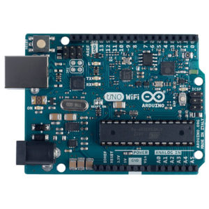
Arduino microcontroller 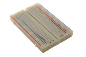
Breadboard 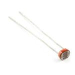
Photocell 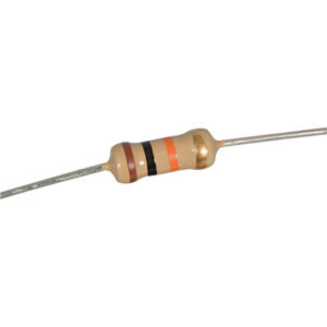
10K resistor 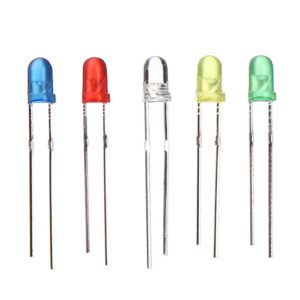
LEDs 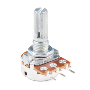
Potentiometer 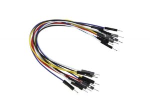
Jumper wires
Measuring Light with a Photocell
Steps and observations:
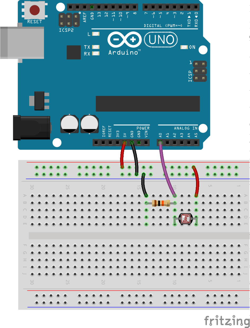
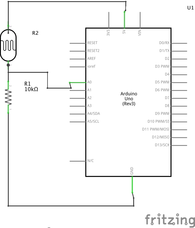
- Build the circuit below (files located in Arduino/Basics/Analog/Photocell/).
- Open the AnalogReadSerial sketch under File->Examples->01.Basics->AnalogReadSerial and upload it to your board.
- Select the Serial Monitor (the magnifying glass icon on the right) and observe the numbers as the light level varies.
- Select the Serial Plotter (Tools>Serial Plotter) and observe a plot of the sensor values.
- Experiment by changing the light levels and moving your hand or another object over the sensor.
- Determine the highest and lowest values observed given the available light levels.
- Observe the noise in the numbers for different constant light inputs.
- Formulate a strategy for calibrating the measurement so that the numbers have a useful semantic meaning. What are useful units for expressing the light intensity? Note: this may be as simple as adding an offset (say 4 or 5) to the lowest reading you observe in order to account for noise. You may also consider using the Arduino map() and/or constrain() functions.
Notes:
The Arduino analog inputs are converted at 10 bits of precision, that is, voltages between 0 and 5V are measured as integer numbers between 0 and 1023, with a nominal resolution of about 4.9 mV per step. However, analog noise in the conversion also limits the precision, so the minimum detectable signal change may be somewhat larger.
The frequency resolution is determined by the sampling rate and the Nyquist-Shannon sampling theorem, which states that a periodic sampling rate must be at least twice as fast as the highest frequency in the input. The Arduino ADC converter runs at a maximum of about 10 kHz, so in principle it can measure signals which vary at up to a 5 kHz rate.
Photocells are relatively slow responding devices (~10-100ms). Rapid light changes and optically encoded data are better measured with phototransistors and photodiodes. However, cheap sensors like these can be adapted to measure many other properties indirectly, e.g. chemicals, dust, mechanical position, proximity, etc.
Breadboard & schematic files can also be downloaded from: https://github.com/carloscastellanos/teaching/tree/master/Arduino/Basics/Analog/Photocell
Add a Potentiometer and LED
Use a potentiometer to control the blink rate of an LED.
Steps and observations:
- Build the circuit below (files located in Arduino/Basics/Analog/Potentiometer_LED/).
- Open the AnalogInOutSerial sketch under File->Examples->03.Analog->AnalogInOutSerial and upload it to your board.
- Observe the blink rate of the LED change as you turn the know of the potentiometer
- Select the Serial Monitor (the magnifying glass icon on the right) and observe the numbers as turn the potentiometer.
- Select the Serial Plotter (Tools>Serial Plotter) and observe a plot of the sensor values.
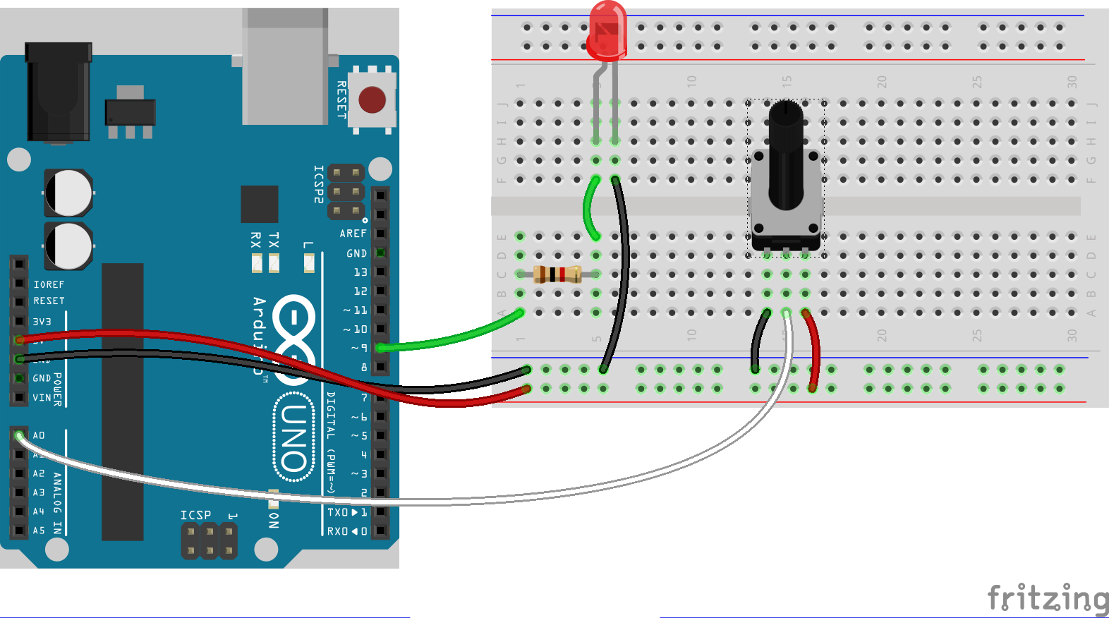
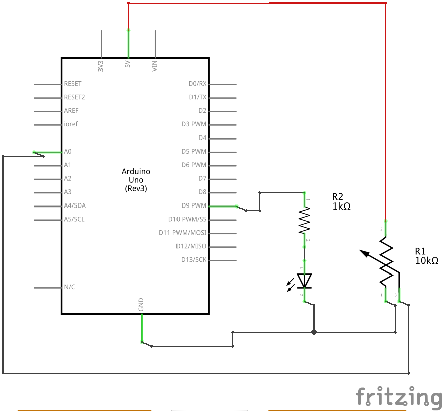
Breadboard & schematic files can also be downloaded from: https://github.com/carloscastellanos/teaching/tree/master/Arduino/Basics/Analog/Potentiometer_LED
Multiple Sensors
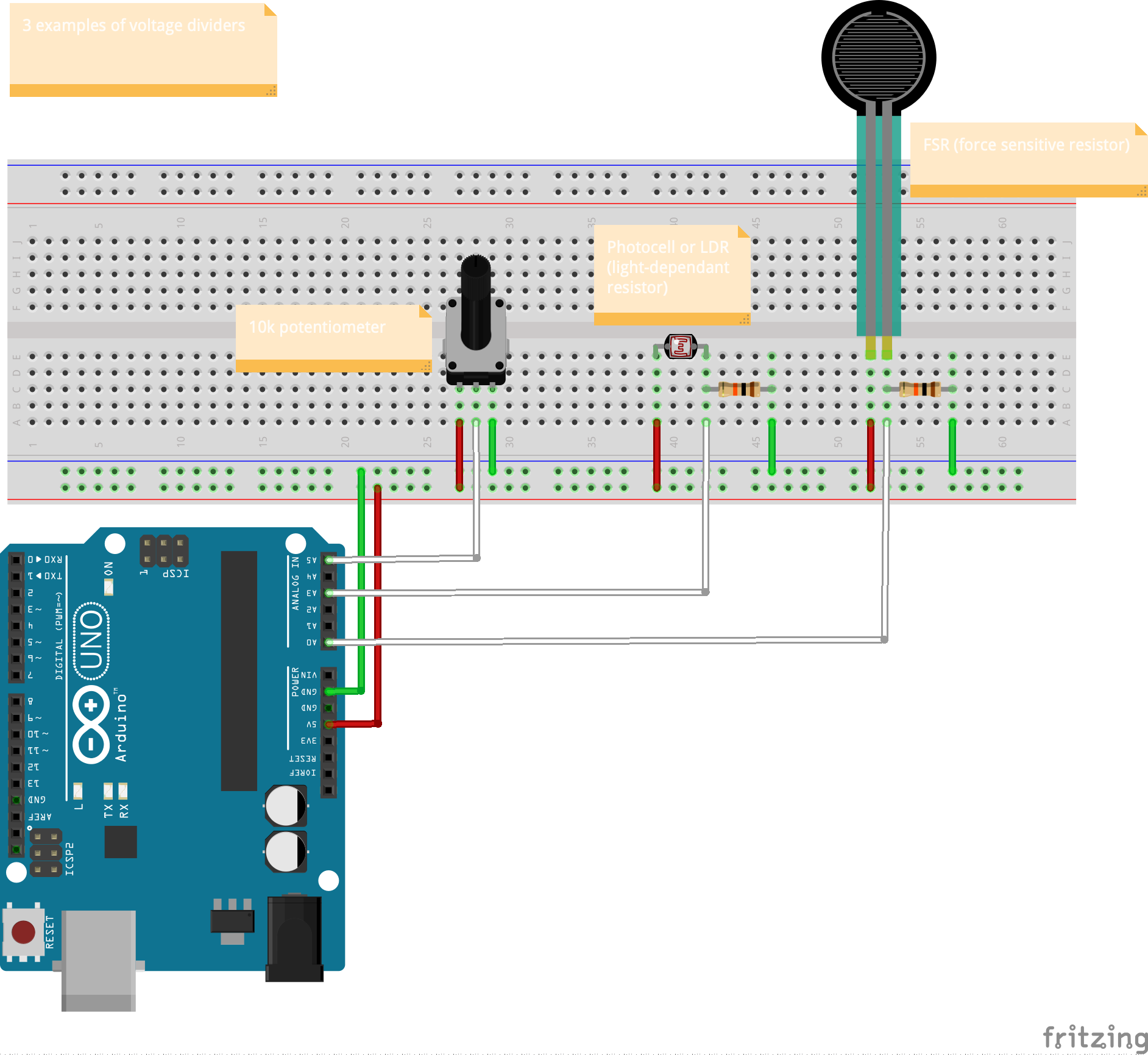
Repeat the steps from the first activity (the photocell) but this time use three analog sensors/voltage dividers. Any 3 that you have handy in any combination is fine. Use the circuit below as a guide.
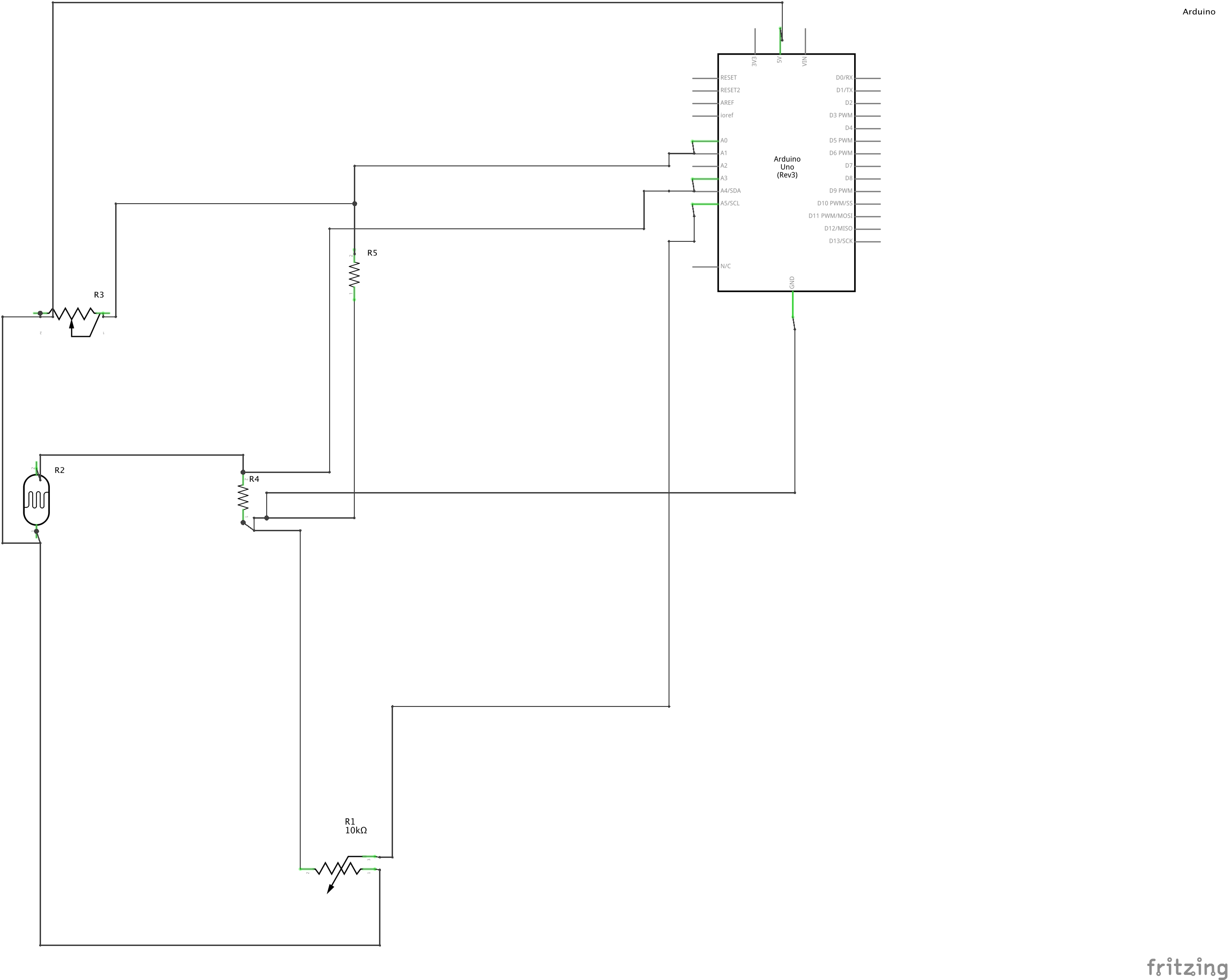
You will also need to write some code to view all three sensor readings clearly in the Serial Monitor. Here is some code to get you started
void setup() {
  // start serial port at 9600 bps
  Serial.begin(9600);
}

void loop() {
  // read sensor values and send them to the serial port:
  Serial.print("sensorPinA0: ");
  Serial.println(analogRead(A0));
  Serial.print("sensorPinA3: ");
  Serial.println(analogRead(A3));
  Serial.print("sensorPinA5: ");
  Serial.println(analogRead(A5));

  delay(1);
}
Breadboard & schematic files can also be downloaded from: https://github.com/carloscastellanos/teaching/tree/master/Arduino/Sensors/multiple_analog_sensors
Other Analog Sensors
You can use many different types of analog sensors and variable resistors for analog input. For example, bend/flex sensors (like those used in the old Nintendo Power Glove), piezoelectric vibration sensors, strain gauges and more. Some orientation sensors (e.g. accelerometer and magnetometer boards) also have analog outputs.
Bonus
Working with microcontrollers starts to get exciting when you have both input devices (i.e. sensors) and output devices (i.e. actuators) connected. When you “map” inputs to outputs, you establish a relationship between something about the environment (e.g. temperature, lighting, distance of an object from a barrier, etc) and some form of actuation (i.e. a robot moving, a sound being triggered, a tweet being sent, etc.). Furthermore, these relationships need not be linear or symmetrical or have the same number of inputs and outputs (i.e. one sensor to one actuator). You can develop all sort of complex rule bases for these relationships. The simple examples just illustrated are a starting point. Can you extend them to do something more interesting and meaningful?
For a challenge try to use the potentiometer (or any analog sensor) to control the blink rate of two or more LEDs. Try to create some kind of pattern by establishing a relationship between the two LEDs and the sensor. For example one LED might blink at twice the rate of another when the sensor value is at 0 but as the sensor value increases the relationships gradually invert (i.e. the other sensor increases its blink rate while the first sensor decreases its blink rate). Can you produce an asymmetric pattern as well? Be creative! Check out this example for inspiration.
Further Reading
Remember to document everything on your blog
Assignment submission is through myCourses.